Arduino pro mini problem without ftdi connected

Thread Starter

qwerty88

Joined Sep 21, 2011
14
Hi

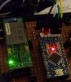
I have an Arduino pro mini powered by a 5V 2A adapter connected directly to the 5v and and pins. I am using an external Arduino Uno (without the MCU) to program the sketch directly to the pro mini (Uno gnd, TX, RX and Reset connected to pro mini gnd, RX, TX and DTR, respectively).
I am using the pro mini eeprom to save data when device is unplugged. Everything works fine with the uno programmer connected to the pro mini device. But when I plug the device without the programmer the code blocks when I compare a local variable with variable got from the EEPROM. But if I press the reset button it works fine again.
I don't understand the relationship between the serial por and this misterious block. I even commented everything using the Serial port (begin and prints) but the problem continues.

Any suggestions?

Best regards.
 

Thread Starter

qwerty88

Joined Sep 21, 2011
14
I found the problem but the cause is completelly stupid and the solution is not working yet.
Basically the programmed makes a reset in the beginning. I don't know why i need that reset but well... i need it.
I tried via software but it doesn't work how i expected. Only works when i physically click the Reset button.

Has someone had a problem similar to this?
 
Edited: Hmm, now I am interested. If I understand you, never mind what I wrote initially. Can you explain further your setup after successful programming? How are you doing the software reset?

I had a problem with a bricked pro mini a while ago and I remember that the road to unbricking went through realizing the the promini needs a reset to activate the bootloader.


____________

Connect arduino uno board RESET pin to pro mini’s RST pin <-- are you doing that? You wrote (Uno gnd, TX, RX and Reset connected to pro mini gnd, RX, TX and DTR, respectively).

See http://www.instructables.com/id/Program-Arduino-Pro-Mini-Using-Arduino-Uno/
 
Last edited:
I can't duplicate what you are seeing. "But when I plug the device without the programmer the code blocks when I compare a local variable with variable got from the EEPROM"

So, when I program a Pro Mini 5V using USB with this code which reads and writes EEPROM:
Code:
#include <EEPROM.h>

int x;
byte value;

// the setup function runs once when you press reset or power the board
void setup() {
  // initialize digital pin LED_BUILTIN as an output.
  pinMode(LED_BUILTIN, OUTPUT);
}

// the loop function runs over and over again forever
void loop() {

  value = EEPROM.read(0);
  if (value != 0)
  {
  for (x = 0; x < 10; x++ ) {
  // fast blink
  digitalWrite(LED_BUILTIN, HIGH);
  delay(300);
  digitalWrite(LED_BUILTIN, LOW);
  delay(300);
  }
  // write addr = 0
  EEPROM.write(0, 0);
  }
  else
  {
  for (x = 0; x < 6; x++ ) {
  // slow blink
  digitalWrite(LED_BUILTIN, HIGH);
  delay(600);
  digitalWrite(LED_BUILTIN, LOW);
  digitalWrite(4, LOW);
  delay(600);
  // write addr = 0
  EEPROM.write(0, 1);
  }
  }
}
It behaves as expected, alternating between fast and slow flashing of the onboard LED.

When I remove the USB and connect Vin (or Vcc) and ground to a separate 5V supply and no other connections, it works fine without having to press reset.

What are you doing differently that could cause the problem that you are seeing?
 
Last edited:

Thread Starter

qwerty88

Joined Sep 21, 2011
14
Hi Raymond.

Thank you for your replies.

The setup is basically what i have in the setup.jpg picture.
Yes i have the arduino uno (no mcu) with its reset pin connected to the pro mini DTR pin (auto-upload), in order to upload a sketch without needing pressing the reset button (so there is the C2 cap between the 2 reset pins -> https://www.arduino.cc/en/uploads/Main/Arduino-Pro-Mini-schematic.pdf).
I am also using the software serial library on pin 4 and 5 to communicate with a BlueSmirf.

Everything is working correctly with the setup like that (with programmer pins touching the pro mini pads + programmer connected to the USB port). The setup also works if i (1) remove the programmer, (2) remove the power adapter, (3) plug the power adapter again, (4) click the reset button. But if i bypass the (4th) step then.... the mysterious problems start. The code works until the part where i compare a value read from the EEPROM with a variable got from the Bluetooth device. The comparison is successful and the program continues if: (1) i click the reset, or (2) i have the programmer already connected (which does the reset when i upload the code).

I solved the problem by connecting a wire between pin 9 and pro mini reset and when i start the bluetooth connection in my phone app, i send a character. When i receive the character i make a software reset:

void setup() {
digitalWrite(9, HIGH);
delay(200);
// initialize the digital pin as an output.
pinMode(9, OUTPUT);
...
...
}
void loop() {
...
//if got character from bluetooth? ->
digitalWrite(9, LOW);
...
}


But this is a stupid way to fix the problem. The problem is still there. I just don't understand where.
When i program the code i have to open the wire between pin 9 and RST, otherwise i can't upload the code... damn!


HERE is the complete code

C:
#include <SoftwareSerial.h>
#include <EEPROM.h>

//PINOUTS
// constants won't change. They're used here to
// set pin numbers:
const int ble_rx_pin = 4;
const int ble_tx_pin = 5;
//RX is digital pin 4 (connect to TX of other device)
//TX is digital pin 5 (connect to RX of other device)
const int debug_led_pin = 12;
const int onboard_led_pin = 13;
const int reset_pin = 9;

SoftwareSerial myBLE(ble_rx_pin, ble_tx_pin); // RX, TX

unsigned int counter_mac_address = 0;

byte mac_address_data[10][6];

byte got_mac=0;

byte mac_got_checked=0;

//EEPROM - 1kb of space
/** the current address in the EEPROM (i.e. which byte we're going to write to next) **/
//|CODE|L|MAC1|MAC2|MAC3|MAC4|MAC5|MAC6|MAC7|MAC8|MAC9|MAC10|CNT|RST
//0    4 5    11   17   23   29   35   41   47   53   59   65   71 72
int code_data_addr = 0;   //4 bytes for data
int code_length_addr = 4; //1 byte for data lenght
int mac_address_addr[10] = {5,11,17,23,29,35,41,47,53,59};    //6 bytes each mac address - 10 macs
int counter_mac_address_addr = 65; //1 byte for 1->10 counter
int reset_addr = 71; //1 byte for 1 or 0 value (

char mac_chars[12]={0,0,0,0,0,0,0,0,0,0,0,0};
char char_num=0;

char current_mac_chars[12]={0,0,0,0,0,0,0,0,0,0,0,0};
int n_receives=0;
unsigned char aux_char=0;
char pos_array=0;

int address_correct=0;
char open_close;

unsigned char character=0;

unsigned long ledtime = 0;
unsigned long bluetooth_mode_time=0, btime, ctime, nltime;

unsigned long decimal_received = 0;
unsigned int length_received = 0;

void setup() {

  digitalWrite(reset_pin, HIGH);
  delay(200);
  // initialize the digital pin as an output.
  pinMode(reset_pin, OUTPUT);
  // Open serial communications and wait for port to open:
  //Serial.begin(115200);
  //LEDS
  pinMode(debug_led_pin, OUTPUT);
  pinMode(onboard_led_pin, OUTPUT);
  digitalWrite(debug_led_pin, LOW); //90 degrees - yellow LED
  digitalWrite(onboard_led_pin, LOW); //SMD led onboard

  //read parameters from EEPROM
  decimal_received=EEPROMReadlong(code_data_addr); //reads 4 bytes from EEPROM
  length_received=EEPROM.read(code_length_addr);   //reads 1 byte from EEPROM
  counter_mac_address=EEPROM.read(counter_mac_address_addr);
  //MAC addresses read from EEPROM
  //60 reads from EEPROM!
  for(int mac_num=0;mac_num<=9;mac_num++){ //10 MACs
    for(int byte_n=0;byte_n<=5;byte_n++){    //6 bytes each
      mac_address_data[mac_num][byte_n]=EEPROM.read(mac_address_addr[mac_num]+byte_n); //reads 1 byte from EEPROM
    }
  }

  //Change RN41 baud rate to 9600 because 115200 is too fast - arduino missed characters
  myBLE.begin(115200);  // The Bluetooth Mate defaults to 115200bps
  myBLE.print("$");  // Print three times individually
  myBLE.print("$");
  myBLE.print("$");  // Enter command mode
  delay(100);  // Short delay, wait for the Mate to send back CMD
  myBLE.println("U,9600,N");  // Temporarily Change the baudrate to 9600, no parity
  // 115200 can be too fast at times for NewSoftSerial to relay the data reliably
  myBLE.begin(9600);  // Start bluetooth serial at 9600
}

void loop() { // run over and over

  static int ledstate = false;

  //NORMAL MODE_____________________________________________________

  //if received stuff from mobile phone ...
  while(myBLE.available()){
    //Serial.write(myBLE.read());
    //SHOULD RECEIVE THIS: <0/1>M<AB:CD:EF:GH:IJ:KL>
    //                       0  1 23456789........18

    character=myBLE.read();
 
    if(character==82){ // 'R'
      //reset MCU
      digitalWrite(reset_pin, LOW);
    }

 
    switch (n_receives){
      case 0: //open_close = myBLE.read();
              open_close=(char)character;
              //Serial.write(open_close);
        break;
      case 1: //myBLE.read();//is M
              //Serial.print(" ");
        break;
      case 2:
        //aux_char=myBLE.read();
        aux_char=character;
        //Serial.write(aux_char);
        //remove ':' from mac_chars and save to eeprom
        if(aux_char!=':'){
          current_mac_chars[pos_array] = aux_char;
          //Serial.write(current_mac_chars[pos_array]);
          pos_array++;
        }
        break;
      default:
        break;
    }
    n_receives++;
    if(n_receives==3)
      n_receives=2;
    if(pos_array==12){
      pos_array=0;
//      Serial.println();
//      Serial.println("END");
   
      got_mac=1;
   
      n_receives=0;
    }
  }
    //should only accept mac known mac addresses
    //if(mac_address==known_list) ....
    //else blink led
  if(got_mac==1){
    got_mac=0;
 
    int pos_aux=0;  //0 to 11
    byte current_mac_chars_hex_value[6]={255,255,255,255,255,255};
    for(int macs=0;macs<10;macs++){  //compare the 10 saved mac addresses
      pos_aux=0;
      for(int pos=0;pos<6;pos++){    //compare each of the 6 bytes
        byte high_nibble,low_nibble;
        high_nibble = h2d(current_mac_chars[pos_aux]);
        low_nibble = h2d(current_mac_chars[pos_aux+1]);
        current_mac_chars_hex_value[pos] = (high_nibble << 4) | low_nibble;
        //................................ENTERS HERE........................................................................
        //FINALLY COMPARE!!!
        if(current_mac_chars_hex_value[pos]!=mac_address_data[macs][pos]){ //if byte doesn't match leave
          //................................DOES NOT ENTER HERE IF THERE IS NO RESET IN THE BEGINNING........................
          pos=6; //to leave interal FOR put an out of boundary position
//          Serial.println("No match.");
       
        }
        else{    //if byte correct and is the last byte then ...
       
          if(pos==5){
            for(int i=0;i<12;i++){
              //Serial.write(current_mac_chars[I]);Serial.print(" ");
            }
            address_correct=1;  //address is correct
            digitalWrite(onboard_led_pin, HIGH);
//            Serial.println("Address OK!");
            macs=10; //to leave external FOR put an out of boundary position
          }
        }
        pos_aux=pos_aux+2;
      }
    }
    mac_got_checked=1;
  }
  if(address_correct==1){
    mac_got_checked=0;
    digitalWrite(debug_led_pin, LOW);
    address_correct=0;
//    Serial.println("SEND CODE!");
// length_received to be used
// decimal_received to be used
  }
  else{ //if address not correct
    if(mac_got_checked==1){
      if (delay_without_delaying(ledtime, 200)) {
        ledstate = !ledstate;
        digitalWrite(debug_led_pin, ledstate);
      }
    }
  }
}
//This function will convert a character representation of a hexadecimal digit into the actual hexadecimal value:
byte h2d(byte hex)
{
        if(hex > 0x39) hex -= 7; // adjust for hex letters upper or lower case
        return(hex & 0xf);
}

//[URL]https://playground.arduino.cc/Code/EEPROMReadWriteLong[/URL]
//This function will write a 4 byte (32bit) long to the eeprom at
//the specified address to address + 3.
void EEPROMWritelong(int address, long value){
  //Decomposition from a long to 4 bytes by using bitshift.
  //One = Most significant -> Four = Least significant byte
  byte four = (value & 0xFF);
  byte three = ((value >> 8) & 0xFF);
  byte two = ((value >> 16) & 0xFF);
  byte one = ((value >> 24) & 0xFF);

  //Write the 4 bytes into the eeprom memory.
  EEPROM.write(address, four);
  EEPROM.write(address + 1, three);
  EEPROM.write(address + 2, two);
  EEPROM.write(address + 3, one);
}
long EEPROMReadlong(long address){
  //Read the 4 bytes from the eeprom memory.
  long four = EEPROM.read(address);
  long three = EEPROM.read(address + 1);
  long two = EEPROM.read(address + 2);
  long one = EEPROM.read(address + 3);

  //Return the recomposed long by using bitshift.
  return ((four << 0) & 0xFF) + ((three << 8) & 0xFFFF) + ((two << 16) & 0xFFFFFF) + ((one << 24) & 0xFFFFFFFF);
}


//[URL]https://forum.arduino.cc/index.php?topic=355651.0[/URL]
boolean delay_without_delaying(unsigned long &since, unsigned long time) {
  // return false if we're still "delaying", true if time ms has passed.
  // this should look a lot like "blink without delay"
  unsigned long currentmillis = millis();
  if (currentmillis - since >= time) {
    since = currentmillis;
    return true;
  }
  return false;
}
Moderators note : used code tags
 

Attachments

Last edited by a moderator:
I don't know what is going on - glad you figured out some kind of work-around, but I don't know. I might go through your code a little deeper and see if I can spot something. In which case, I will let you know.

In the meantime, take a look at this link https://www.codeproject.com/Articles/1012319/Arduino-Software-Reset specifically the hardware reset method.

Edited to add, I don't know if it is the EEPROM at all. It could be the bluetooth board ( accordng to the schematic, the reset pin is not brought out to anything).
 
Last edited:

Thread Starter

qwerty88

Joined Sep 21, 2011
14
That would be great.
Well yes it can be other module besides the EEPROM. It is just that it blocks in that part of the code.
I will take a look at that link
 
Top