Arduino interface with 24v Thermostats

Thread Starter

haukeg

Joined Dec 9, 2018
66
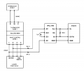
After a long holiday break, I am back on this challenge. I reviewed a number of posts on the HPCL-3700 + Arduino and found some circuits that looked promising. Attached is what I assume is correct, but wanted to see if anyone sees any issues with resistor values or other details.

One thing I am not sure of is if I need to add a capacitor to the DC+ & DC- on the optocoupler or not? That was referenced in a post here.

Thanks again for all the help thus far.
 

Attachments

Thread Starter

haukeg

Joined Dec 9, 2018
66
I have tested my circuit design, but for some reason, it is not performing as expected. I have a simple Arduino Sketch watching for my digital pin (connected from pin 6 on the HCPL-3700) to switch from HIGH to LOW, but nothing changes when the 24v comes into pin's 1 & 4. I have the 10 uF cap on 2 & 3, 20k resistors on the lines to 1 & 4, and the 10k resistor between Vcc (pin 8) and Vo (pin 6). I have my Vcc (pin 8) connected to the 5V pin on my Arduino and the GND (pin 5) to GND on Arduino, as shown in the circuit design.

I assume I should do some testing to figure out if things are configured as expected. I wonder, what should I be expecting to come from pin 6 (Vo) when 24v comes across Pin 1 & 4. Can I check with a voltmeter for something perhaps? Maybe my resistance values or the cap are an issue? I have seen some designs calling for a cap between pin 8 (Vcc) and pin 5 (GND)? Any other thoughts? Thanks for any assistance.
 

dendad

Joined Feb 20, 2016
4,641
Do you have a LED with series resistor on the input port as an indicator?
It is a good idea to include that. If thew LED comes on but you cannot read it, than the code may be in question. What is your code?
 

Thread Starter

haukeg

Joined Dec 9, 2018
66
I leveraged the LED on pin 13 on my Arduino board, the code is below. I first tested this sketch using a pull-up & pull-down circuit example I found online (see attached) to confirm that the logic was working before connecting to the heating system - and it worked as expected.

C:
const int inputPin = 8;  
const int ledPin = 13;    
int pinState = 0;

void setup() {
  pinMode(inputPin, INPUT);
  pinMode(ledPin, OUTPUT);
  Serial.begin(9600);
}

void loop() {
  pinState = digitalRead(inputPin);
  if (pinState == HIGH) {
    digitalWrite(ledPin, HIGH);
    Serial.println(pinState);
  } else {
    digitalWrite(ledPin, LOW);
    Serial.println(pinState);
  }
  delay(50);
}
 

Attachments

Last edited by a moderator:

dendad

Joined Feb 20, 2016
4,641
For a start, you have 40K in series with the 24VAC (2 x 20K).
think that is way too high. In would try 1 x 2K2 resistor instead. And add a 220R resistor in series with an LED from +5V to pin 8 for an indicator.
 

Thread Starter

haukeg

Joined Dec 9, 2018
66
Well I am stumped. I dug in deeper and read this more comprehensive interface spec on the HCPL-3700, which I found very informative. In the end, I followed the configuration for Example 2 (AC Operation) along with the following Input Filtering for AC Operation to add the 10uF cap for ripple suppression.

After doing the calcs on resistance on pages 5-7, Rx = V+ - Vth+ / Ith+ along with the specification for calculating RMS at 65% when using a capacitor for ripple (specified on page 7), I got 24vRMS * 0.65 = 15.6v for V+, Vth+ is specified as 5.1 and Ith+ is 2.5: Rx = 15.6 - 5.1 / 2.5 = 4.2kOhms for resistance total on pins 1 & 4 (AC) - so split, 2.2 on each leg. This didnt work, so I checked the voltage I was getting at pin 1 & 4 when I connected my 24v and it was just over 6v, which seemed a touch out of spec of 5v for the Vth+ (input upper voltage threshold level). So I increased resistance slightly to 6.6kOhms total which brought my voltage at pin 1 & 4 down to 5v (perfect). After checking for logic on the other side (pin 6), I get still got nothing. I tested pin 6 as well with my voltmeter, assuming I would see some voltage when I expected logic out, but it stayed at 0. (I tried the LED with resistance from pin 6 on the HCPL-3700 and got nothing of course, since no voltage was coming out)

Any thoughts? Thanks!
 

dendad

Joined Feb 20, 2016
4,641
I assume you do have the circuit connected up as in post #21 so there is +5V and GND from the Arduino?
Did you add an LED with a 330R series resistor across the 10K resistor so you can get a visual indicator?
Also, try it with the LED but without the Arduino I/O pin connected.
 

Thread Starter

haukeg

Joined Dec 9, 2018
66
The only difference from the design in #21 is that I removed the 10kR connecting Vcc and Vo back to the Arduino, because the specifications in Figure 6 of the more comprehensive interface spec did not call for that. I have attached Figure 6.

I did try to connect an LED with and without the Arduino connections but got nothing.

In any case, wouldn't I see some kind of voltage come from pin 6 of the HCPL-3700 if the detector side switched? I saw nothing in any case which leads me to believe I am not triggering the detector side for some reason?
 

Attachments

Reloadron

Joined Jan 15, 2015
7,892
Tie a 10K resistor between pin 6 (Vout) and pin 8 (VCC). The HPCL3700 has an open collector output. That or set the digital input of the Arduino for an internal pull up.

I also looked at your code:
Code:
const int inputPin = 8; 
const int ledPin = 13;   
int pinState = 0;
void setup() {
  pinMode(inputPin, INPUT);
  pinMode(ledPin, OUTPUT);
  Serial.begin(9600);
}
void loop() {
  pinState = digitalRead(inputPin);
  if (pinState == HIGH) {
    digitalWrite(ledPin, HIGH);
    Serial.println(pinState);
  } else {
    digitalWrite(ledPin, LOW);
    Serial.println(pinState);
  }
  delay(50);
}
OK, so your input pin is pin 8. Now if you want to use an internal pullup you would change the code to read:
Code:
pinMode(inputPin, INPUT_PULLUP);
Either way the open NPN output of the chip needs a pull_up or all we have is an open collector just hanging out there.

Ron
 
Last edited:
I'm going to suggest this http://www.gravitech.us/busio.html the only real problem is it's big. The AC module is cheap and so is the backplane, It's a pretty nice system.

The AC input module doesn;t work for 24 VAC, but a few component changes and it should. It's basically limiting the current with a reactive impedance to drive the LED, not resistive.

The industrial way to do this is to use I/O modules such as these: http://www.crydom.com/en/products/digital-i-o-modules/ Some are stand alone, some DIN rail mountable, some have a backplane but they handle 24 VAC and they are not cheap.

You'll find modules with different logic power supplies too.

I would have responded sooner, but I forgot the name of the product.
 

Thread Starter

haukeg

Joined Dec 9, 2018
66
@Reloadron Thanks Ron, that did the trick. I can't believe it was the simple 10K resistor that got me, and I even had it in my original design. I omitted it after digging in deeper on that interface spec. Well, in any case, this seems to be working well, I got the HIGH/LOW values expected on pin 8 on my Arduino sketch. Now I will work to scale this out to all 5 zones and design a reporting program. I really appreciate all your help to this point, you were a key in my success, many tips you gave steered me to this point and for a novice it was a big help. Now I only wish I fully understand what happened and why. You explaining the pull-up requirement sort of makes sense, but it really doesn't. Time to go to EE school.

Cheers!
 

Reloadron

Joined Jan 15, 2015
7,892
this thread has many loops, can you please post the final design so I can build a couple, thank you, Tj
This thread only has thirty five post from beginning to end. The project was built around using a HCPL-3700 Interface Optocoupler to create an interface between an available signal and a micro-controller. There isn't too much else to say or draw about what was done.

What exactly is the goal of your project and what parts do you plan to use. You toss out a basic diagram and project description and someone here will help you. Unless your project is absolutely identical to what was done here I suggest you start a new thread. Be specific.

Ron
 

Phil-S

Joined Dec 4, 2015
241
The tricky part of this project is getting the various resistors and filter capacitors correct on the input side of the HCPL3700 or HCPL3760 (last one recommended for greater sensitivity). You can use a DC or AC source on the input (see datasheet and the various application notes - look at all the manufacturers as some have better ANs than others).
All that is happening is the front end of the HCPL has a bridge rectifier and it feeds the rectified AC or the DC input to an internal LED and a matched amplified detector. The resistors set the voltage levels that the detector will pick up the LED output. The calculations, especially if you throw in hysteresis, are complicated, even if you use a spreadsheet. I found trial and error works best, plus the graphs in the datasheet. Get initial resistor values that definitely pick up your input voltage, then tweak them back. I aim to get the highest resistor values that will work. I think from memory that 2 x 27K 2-W worked well for 240-V AC and a 10K capacitor. At 240-V, the resistors can get pretty warm and for safety, I might use 5-W ceramics. 24-V AC should be straightforward. The open collector output does need to pulled up as mentioned above and gives you an active low when your input is high. Personally, I think an external pull-up like 10K is a better and more predictable result than the internal pull-ups on the Arduino, assuming that is what you want to use. A very useful chip once you've got it working.
 
Top