Arduino and ESP8266-01 serial communication (5V to 3.3V)

Thread Starter

zazas321

Joined Nov 29, 2015
936
Hello. I am trying to do some excersises with ESP8266-01.

http://geonosiansnotes.blogspot.com/2016/06/arduino-uno-and-esp8266-esp-01-led.html

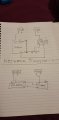
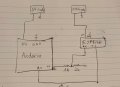
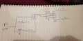
I am trying to follow this guide but its clear for me that I should not be able to connect RX and TX from arduino directly to ESP8266-01 as this device operates on 3.3V. I did measure my Arduino uno RX and TX pins and I was able to identify that it is 5V rather than 3.3V though most of the guide online show direct connection between arduino and ESP8266. Would you guys suggest me any simple ways how to turn Arduino RX and TX pins into 3.3V so I can connect it to my ESP-8266 and if I change the RX and TX voltage levels, is there any drawbacks to it? would I still be able to program my arduino as I was before?

Also, I should mention that I have an FTDI 3.3V adapter and I am able to program my ESP8266-01 using it. But I want to be able to use my arduino with it.
 

Thread Starter

zazas321

Joined Nov 29, 2015
936
Okay, so i have built a potential divider with 1k and 2k resistors. I do get some very strange measurements. When I measure my arduino TX voltage, I get 4.8V when its not connected to a potential divider. When i connect to potential Divider, I only measure 0.48V at pin TX which is no use to me.
I have made the connection as shown below just using arduino UNO isntead of nano


Thread Starter

zazas321

Joined Nov 29, 2015
936
I have just ordered one of those. I will see whetger I get some reasonable results. Though i am very confused why my tx pin voltage drops so much when i add potential divider to it
 

LesJones

Joined Jan 8, 2017
4,511
From you diagram it looks like you are using the arduino to route data through from the USB to serial converter (FT232RL) using a software UART to feed it to the ESP8266. I think the software in the Arduino will be too slow for the programming to work. I suggest using the TX and RX directly from the FT232RL. You will need to load the arduino with a sketch that DOES NOT enable the serial port. One of the blink sketches will do. You will still need your level converter. You will connect your blue wire to the RX pin on the arduino board. (NOTE This is TX from the point of view of the RT232RL) You will need to connect your your green wire to the TX on the Arduino. (NOTE this is the RX from the point of view of the RT232RL.

Les.
 
Last edited:

Thread Starter

zazas321

Joined Nov 29, 2015
936
When I use arduino, I do not use ftdi with it. Using FTDI I am able to flash tge ESP8266, but when I try to use Arduinl UNO i get some memory error. I suspect it could be because of my TX voltage going low when connected to potentisl divider. ESP8266 is not able to recognise such low voltage levels therefore not letting me program.
 

Attachments

LesJones

Joined Jan 8, 2017
4,511
There seems to be conflicting information in your posts. You show a Nano but talk about the Uno. In one drawing you show that you are using D2 and D3 connections. In another you show that you are using the RX and TX connections.

Les.
 
Last edited:

Thread Starter

zazas321

Joined Nov 29, 2015
936
The picture with nano is the circuit that I got from the internet. Sorry to confuse you. I am using the circuits that I have posted in the previous message
 

LesJones

Joined Jan 8, 2017
4,511
Can you say EXACTLY how you are trying to program the ESP8266.
1 Is it an Uno or a Nano ?
2 Are you running any software (Sketch in Arduino terminology.) ? If so what and if so describe how it works. (As I am totaly useless at programming in "C") (I want to know if the arduino is communicating with the PC via a USB to serial converter and it's hardware USART and communicating with the ESP8266 via a software UART.)
3 If it is a Uno have you removed the Atmega328p from it's socket ?
4 Show EXACTLY how RX and TX from the ESP8266 are connected to the Arduino.

Les.
 

Thread Starter

zazas321

Joined Nov 29, 2015
936
1. I am using arduino UNO

2. I am using Arduino software to upload a program to both (FTDI to USB adapter and Arduino UNO) code below:


C:
/*
* This sketch demonstrates how to scan WiFi networks.
* The API is almost the same as with the WiFi Shield library,
* the most obvious difference being the different file you need to include:
*/
#include"ESP8266WiFi.h"
void setup(){
Serial.begin(115200);
// Set WiFi to station mode and disconnect from an AP if it was previously connected
WiFi.mode(WIFI_STA);
WiFi.disconnect();
delay(100);
Serial.println("Setup done");
}
void loop(){
Serial.println("scan start");
// WiFi.scanNetworks will return the number of networks found
int n =WiFi.scanNetworks();
Serial.println("scan done");
if(n ==0)
Serial.println("no networks found");
else
{
Serial.print(n);
Serial.println(" networks found");
for(int i =0; i < n;++i)
{
// Print SSID and RSSI for each network found
Serial.print(i +1);
Serial.print(": ");
Serial.print(WiFi.SSID(i));
Serial.print(" (");
Serial.print(WiFi.RSSI(i));
Serial.print(")");
Serial.println((WiFi.encryptionType(i)== ENC_TYPE_NONE)?" ":"*");
delay(10);
}
}
Serial.println("");
// Wait a bit before scanning again
delay(5000);
}
3. I have not removed the chip from its socket, however, I have grounded a RESET pin to bypass arduino UNO and program ESP8266 instead.


4. I have simply used 1k and 2k resistors to make a potential divider to shift a logic level of TX arduino pin from 5V to 3.3V, however, as I mentioned above, when I connect my TX pin of arduino to 1k resistor, the voltage suddenly drops from 4.8V to 0.48V


The error I get when I try uploading a code is:
error: espcomm_upload_mem failed

Moderators note : Please use code tags for pieces of code
 

Attachments

Last edited by a moderator:

LesJones

Joined Jan 8, 2017
4,511
As you are disabling the the Atmega328p you are just using the Atmega16u which is doing the USB to serial conversion.It's RX pin is connected to the Atmega328's TX pin and the atmega16u is connected to the RX pin on the Atmega328. The connections on the Uno board are labled to match the Atmega328's Rx and TX pins. So the RX connection on the board is actualy the TX pin on the Atmega16u. Because of this you have to connect the Arduino RX pin to the RX pin on the ESP8266. (and the same with the TX pins.) So from your drawing in post #10 you just need to swap over the RX and TX connections to the Arduino. That should also fix the problem with your potential divider pulling down the voltage on the TX line.

Les.
 

Thread Starter

zazas321

Joined Nov 29, 2015
936
Hey LesJones! I have swapped rx and tx and it works ! Im able to program ESP with arduino though im still not entirely sure how it works. I am pretty sure I have programmed something in the past by connecting reset pin to GND and then using RX and TX respectively. Also, I was not aware that Arduino have more than 1 main chip, so if you disable 1, the other one will be used? Also, does software serial library that lets me change rx and tx pins change something in that case, would I still be able to program
 

LesJones

Joined Jan 8, 2017
4,511
There is only one main chip an the Arduinos that I have seen. The other chip us to convert the USB signal to serial data. The Nano in your picture yesterday uses an FT232RL to do this. The Uno uses an Atmega16U for this purpose. If you look in device manager on your PC you will see it has created a virtual comm port. You are only using the part of the Aduino board that does the USB to serial conversion. One thing I could not get to work was using a real serial port on the PC to program an ESP8266. The software serial library creates a UART in software and should be able to use any digital I/O pins. It has to do a lot more work than using the hardware USART. It has to do serial/parallel conversion and the timing input and output the bits. Using the USART all it has to do is check that the TX buffer is empty and if it is then write a byte of data to it. For receive it just checks the data available bit and if it is set it reads the byte of data from the RX buffer. I sometimes use the Arduino Uno for configuting Bluetooth modules and I just unplug the ATMEGA328 chip.

Les.
 

Thread Starter

zazas321

Joined Nov 29, 2015
936
Thank you for all help and detailed answer. One quick question though- if i take atmega chip out of arduino UNO , would I need to connect TX to RX and RX to TX rather than RX to RX and TX to TX
 

LesJones

Joined Jan 8, 2017
4,511
It would not change any thing. Remember it is the RX and TX on the atmega16u (USB to serial converter.) that are talking to the ESP8266 so the TX on the ATmega16U needs to connect to the RX on the ESP8266. BUT when programming the ATmega328p The TX on the Atmega16 u has to be connected to the RX on the Atmega328p and the RX marking on the board is the RX on the Atmega328p BUT THAT IS THE TX on the Atmega16u. If you lookk at the schematic of the Arduino Uno it may help you to understand.

Les.
 

Thread Starter

zazas321

Joined Nov 29, 2015
936
So I am looking at this schematic diagram:


I can see that Arduino RX and TX pins of atmega328 are connected to m8rxd and m8txd pins of atmega16u.


I am not fully understanding the idea of having atmega16u to do to serial to usb conversion for atmega328 chip. Why serial to usb conversion cannot be directly done by atmega328?
 

LesJones

Joined Jan 8, 2017
4,511
The bootstrap loader in the Atmega328p expects code to be loaded from the serial port. (NOTE The Atmega328p is not just a blank chip straight from the manufacturers. The bootloader code has to be loaded into it using normal programming methods before it will work in an Arduino.) It may be possible to write a bootloader that would work directly with the USB but it would take up much more memory in the Atmega328P which would leave less space for user programs.You would first need to look at the datasheet for the Atmega328p to see if it can support a USB interface and then contact the Arduino designers and ask them why they did not design it to load directly from the USB. Try yourself to write a sketch to make the Arduino Uno communicate directly with the USB. I think you will find it very hard.

Les.
 

Phil-S

Joined Dec 4, 2015
241
The bootstrap loader in the Atmega328p expects code to be loaded from the serial port. (NOTE The Atmega328p is not just a blank chip straight from the manufacturers. The bootloader code has to be loaded into it using normal programming methods before it will work in an Arduino.) It may be possible to write a bootloader that would work directly with the USB but it would take up much more memory in the Atmega328P which would leave less space for user programs.You would first need to look at the datasheet for the Atmega328p to see if it can support a USB interface and then contact the Arduino designers and ask them why they did not design it to load directly from the USB. Try yourself to write a sketch to make the Arduino Uno communicate directly with the USB. I think you will find it very hard.

Les.
Nick Gammon covers all this in depth on his website.
The Nano clones use the cheaper CH340 serial to USB chip instead of the FTDI chip.
There is a problem uploading to the clones which had me fooled for a while.
In the IDE tools menu, under processor for the Nano, there is an extra item "use old bootloader".
That needs selecting then it all works. I don't know if this applies to all clones, but the Elegoo clone I use won't work on the default processor.
 

Thread Starter

zazas321

Joined Nov 29, 2015
936
Hello guys. I have been experimenting with my ESP8266 and arduino. Unfortunately I am not able to program my ESP8266 using softwareSerial. I am able to program/flash some basic code to my ESP8266 by using Arduino pins D0 (RX) and D1 (TX) and connecting them to ESP. I am trying to upload the same program just using SoftwareSerial pins 2 and 3 instead of 1 and my ESP8266 does not react at all. All I did was change arduino wires instead of D0 and D1 to D2 and D3 and added 3 lines of code..

Perhaps I am not quite understanding the SoftwareSerial?

The code that I use:

C:
#include <SoftwareSerial.h>
SoftwareSerial esp8266serial(2,3); // make RX Arduino line is pin 2, make TX Arduino line is pin 3./*

#include "ESP8266WiFi.h"

void setup() {
esp8266serial.begin(115200);
Serial.begin(115200);
  // Set WiFi to station mode and disconnect from an AP if it was previously connected
  WiFi.mode(WIFI_STA);
  WiFi.disconnect();
  delay(100);

  Serial.println("Setup done");
}

void loop() {
  Serial.println("scan start");

  // WiFi.scanNetworks will return the number of networks found
  int n = WiFi.scanNetworks();
  Serial.println("scan done");
  if (n == 0) {
    Serial.println("no networks found");
  } else {
    Serial.print(n);
    Serial.println(" networks found");
    for (int i = 0; i < n; ++i) {
      // Print SSID and RSSI for each network found
      Serial.print(i + 1);
      Serial.print(": ");
      Serial.print(WiFi.SSID(i));
      Serial.print(" (");
      Serial.print(WiFi.RSSI(i));
      Serial.print(")");
      Serial.println((WiFi.encryptionType(i) == ENC_TYPE_NONE) ? " " : "*");
      delay(10);
    }
  }
  Serial.println("");

  // Wait a bit before scanning again
  delay(5000);
}
 

Attachments

Top