Facebook
 Google
 GitHub
 Linkedin
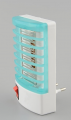
I need a very simple inverter from 4 volt dc to 220 volt ac. the load is extremely low ( less that 3 Watt and only for few seconds at a time). So, I went to "ytube"and discovered zillions of circuits NONE worked !!!!. I will go from today to a month back ( if needed):
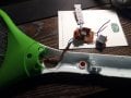
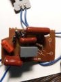
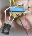
1. Got High frequency transformer ( Two Primary and one secondary) Let us call them P1 P1 and S. I did all the measurements to make sure that the three coils are working ( multimeter tests). The simplest circuit use one low resistance ( 30-100 ohm) and an NPN transistor. I tried so many Transistors NONE of them worked. The schematic is extremely simple See att. And I will summerize it here:
top side we have four pins: P11 P12 P1 P22 and Two pins on the other side: S1 S2 :
P11-P12 to the load 220 volt ac
P21 to Base of the NPN transistor
P22 to S12 Resistor ( 330 -100 ohm)
S11 to Collector
Emitter to -ve of the 4 volt Battery and S12 is the +ve of the Battery.
I tried 2 transistors: TIP122 and TIP41C and 2N3055.
Your help in debugging this extremely simple circuit will be greatly appreciated.
P.S. You will notice in the att. The transistor used is D822 which I do not have. And I hope it is not the issue here. Any NPN transistor will do.
As I said in the title anyone worked with this "empirical" circuits will be able to give me a hand. The reason I am saying this; is because there is no "math" behind it.!!!!
Attachments
-
 248.5 KB Views: 22