 Facebook
 Google
 GitHub
 Linkedin
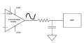
Hi, i'm i've build an circuit, ilustrated in the bellow figure, which its purpose is to sample an Sine Wave of 1kHz sourced by an InAmp (AD8226) with an ADC from a uC (Pic18f26j13) with maximum Fsampling= 40 kHz . This adc has 12 bit and its voltage reference is 3V.
When i designed the following circuit i added an passive anti-aliasing filter but i was reckless and i didn't know very well what i was doing. So i projected with some values that i realize now that were totally wrong and this is where I'm now and a little desperate for some help.
Because first of all, the AD8226 requires that the time constant of this RC filter would be slower than 5uS. I was told if i wanted to achieve the ADC's resolution (12 bits) i would want to achieve a settling time when the filter reaches an magnitude of 74 db (6.02N+1.76 dB) . This means i would need to wait between samples 8.6*RC , which would lead to 23kHz (8.6*5us). Is this correct ?
On the other hand i also read in other discussion forum that with a 23kHz the maximum sampling frequency i would be limited to filtering a signal of half of this frequency , 11.5 kHz. And with a passive filter i should get a -20dB around this 10kHz, thus i should set the corner frequency to 1.15kHz.
But if this is true i would be filtering or very close to filtering my 1kHz signal frequency too, degrading the signal.
I was wondering what would be the cost of letting go the RC filter and just connect the Inamp directly to the adc ?
Its a huge mess, can someone shed some light over this mater, all i want is to try to not compromise the 12 bit resolution of the ADC and keep a minimum 5uS time constant of the filter to not compromise my InAmp Stability.
Thank you
Attachments
-
 15.5 KB Views: 10


")


