AND gate with a ?pull-down resistor?

Thread Starter

Dimitri555

Joined Apr 16, 2023
6
Hello everyone,

I am new to the field of electronics and am just getting to grips with Logic Gates. And it's the AND Gate that's giving me problems right now :) I found a circuit diagramm for it on the following website:

https://electronics-fun.com/logic-gates/

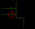
According to the truth table, the output should be 0 even if one of the inputs is 1. I build this circuit diagramm using Paul Falstad's Circuit Simulator (https://www.falstad.com/) and unfortunately the output is 1 when the second switch (see Pic_1) is closed.

I then researched for a solution and came across this YouTube video:


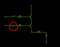
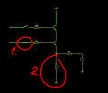
I rebuilt this circuit diagramm again using Paul Falstad's Circuit Simulator and it works correctly (see Pic_2).

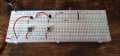
I also rebuilt this circuit on a breadboard and it works (see Pic_3)

As far as I can understand, the part marked in red (Pic_2, 2.) is a pull-down resistor. I have read some articles about the pull-down resistors and still can't understand why the LED is not lit in this case. I would be very grateful for an explanation.

Thanks in advance!

Best regards,
Dimitri

PS: Sorry for the possible language mistakes, I am not a native English speaker.
 

Attachments

Alec_t

Joined Sep 17, 2013
14,430
Welcome to AAC!
In Pic 2 only one switch (1) is closed. Close both switches (so that both inputs of the AND gate are at logic high) and the LED should light.
 

ericgibbs

Joined Jan 29, 2010
19,168
Hi Dimitri,
Welcome to AAC.
Using a 270 Ohm resistor to the Base of the lower transistor will light the LED.
The current path is 5V > base voltage drop of 0.7V will apply 4.3V volts across the LED circuit, it will light.
270 Ohm value is too low.
E

Added:
EG57_ 1012.png
 

crutschow

Joined Mar 14, 2008
34,908
Your first circuit is a faulty design (unfortunately there's a lot of crap electronic designs on the internet).
In that circuit, when voltage is applied to the bottom transistor, there is about 4mA current through the base-emitter junction due to the small base resistor value, which then goes through the LED, lighting it (the base-emitter junction looks like a forward-biased diode).

In the second circuit, the base resistor value is much higher so the current is lower, and the pull-down resistor can carry that current and keep the voltage below the turn-on value of the LED.

Make sense?

Your English is fine.
 
Last edited:

Thread Starter

Dimitri555

Joined Apr 16, 2023
6
Thanks you all a lot for your feedback!

@crutschow , I'm not quite sure how you came up with the 4mA... Paul Falstad's simulator also says that it is 4.873 mA...

But I would have calculated it as follows (in case of the first switch being open and the second one closed):

V = 5
R1 (base resistor of the second transistor) = 270
R2 (resistor before the LED) = 270
I = V / R1 + R2 = 5 / 270 + 270 = 0,0092A
 

Thread Starter

Dimitri555

Joined Apr 16, 2023
6
Ohh, thanks guys! Now it makes sense to me!

However I'm still confused about the second part of @crutschow 's statement:

"In the second circuit, the base resistor value is much higher so the current is lower, and the pull-down resistor can carry that current and keep the voltage below the turn-on value of the LED."

I tried to calculate it and came up with the following result:

Vs = 5
Vbe = 0.7
Vf = 2
R1 = 10.000

R2 = 1.000
R3 = 1.000

Since R2 and R3 are in series the total resistance is:

1/Rtot = 1/R2 + 1/R3 = 1/1.000 + 1/1.000 = 500

I then tried to calculate the total current:

I = (5 - 0.7 - 2) / (10.000 + 500) = 0.000219 A

However Falstad's Simulator says it's 400.969μA.

Can you possibly help me further here?
 

Thread Starter

Dimitri555

Joined Apr 16, 2023
6
I meant the second case where the base resistor of the second transistor has 10,000 Ohm and the pull-down resistor has 1,000 Ohm and the resistor before the LED also has 1,000 Ohm (see Pic_2).
 

MrChips

Joined Oct 2, 2009
31,183
I meant the second case where the base resistor of the second transistor has 10,000 Ohm and the pull-down resistor has 1,000 Ohm and the resistor before the LED also has 1,000 Ohm (see Pic_2).
In the second case, the base-emitter current is relatively low and can be ignored.
If we ignore the collector-emitter voltage, the current through the pull-down resistor is 5V/1kΩ = 5mA.
The current through the LED is (5V - 2V)/1kΩ = 3mA.
 

crutschow

Joined Mar 14, 2008
34,908
I then tried to calculate the total current:

I = (5 - 0.7 - 2) / (10.000 + 500) = 0.000219 A

However Falstad's Simulator says it's 400.969μA.

Can you possibly help me further here?
Your are making blind calculations without thinking about what state the circuit may be in.

If the top transistor is off, then let's start by assuming the circuit is correctly working and the LED is also off (thus we can ignore the LED connection).
Then the emitter current of the bottom transistor is approximately (5-0.7) / (1k + 10K) = 391µA (the simulator gave 401µA, close enough).
This give a voltage across the 1k resistor of about 0.4V which, of course, is not enough to turn on the LED so no current goes through the 1k LED resistor, (thus verifying our original assumption).

Make sense?
 
Last edited:

crutschow

Joined Mar 14, 2008
34,908
Just for curiosity, I plotted the current for a Red LED for various values of the emitter to ground resistor (R1) value with the top transistor OFF and the bottom one ON (below):
It shows that, for a Red LED, there is no significant LED current (yellow trace) until R1 goes above about 3kΩ.
Thus R1 could be increased some to minimize circuit power.

1690741797693.png
 

Thread Starter

Dimitri555

Joined Apr 16, 2023
6
Hi guys, I still have some questions ;)

What I can't understand is why we need the pull-down resistor at all? Because, if I understood correctly, it is used when you don't want the input (i.e. the LED in our case) to be floating.

But,

first: The input is not "floating", it is connected to the lower transistor. Or am I misunderstanding something here?

second: If you increase the value of the base resistor to e.g. 50 kOhm (see Pic_4), some current flows to the LED, but not enough to make it light up. In this case the AND gate works as it should. So, it doesn't really make sense to add a pull-down resistor...

Thanks in advance for your response!
 

Attachments

djsfantasi

Joined Apr 11, 2010
9,189
first: The input is not "floating", it is connected to the lower transistor. Or am I misunderstanding something here?
I don’t know what you think the inputs are, but I think they are the base connections to the transistors. When either/or/both switches are open, the connections to the transistor bases are floating. Hence you need a pill-down resistor from the bases to ground.
 

WBahn

Joined Mar 31, 2012
30,335
Hi guys, I still have some questions ;)

What I can't understand is why we need the pull-down resistor at all? Because, if I understood correctly, it is used when you don't want the input (i.e. the LED in our case) to be floating.

But,

first: The input is not "floating", it is connected to the lower transistor. Or am I misunderstanding something here?

second: If you increase the value of the base resistor to e.g. 50 kOhm (see Pic_4), some current flows to the LED, but not enough to make it light up. In this case the AND gate works as it should. So, it doesn't really make sense to add a pull-down resistor...

Thanks in advance for your response!
The INPUT to the AND gate are the two signals on the left. The OUTPUT is the bottom of the lower transistor (the emitter).

1691604367699.png

To be a proper logic gate, the circuit has to be able to be driven by other gates of the same type and be able to drive other gates of the same type. Otherwise, you might have a circuit that implements an AND function in a particular situation, but you don't have an actual logic gate.

In this circuit, if both inputs are disconnected, then the transistor bases are floating and there can be leakage currents that could be enough to result in a subsequent gate's input being pulled sufficiently high to turn on that transistor. So a pulldown resistor is needed on the output to establish a firm logic LO whenever both inputs are LO.
 
Top