Analog Multiplier Calculation

Thread Starter

Saviour Muscat

Joined Sep 19, 2014
187
Hello,
Hope this thread finds you in good health,

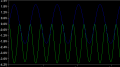
I simulated an analog multiplier(shown on an academic paper by Riewruja2011, Four-quadrant analog multiplier using operational amplifier ) with LTspice, by multiplying two analog sinewaves in which the resulting signal was correct.

I need to get "Is"(class AB bias current ) from LT spice simulated circuit(program attached) using "universal op-amp2".
 

Attachments

Last edited:

crutschow

Joined Mar 14, 2008
34,280
I need to get "Is"(class AB bias current )
Are you referring to the op amp bias current?
Class AB normally refers to a push-push pull output stage with a small bias current.

The op amp bias current can be measured after a transient simulation by putting the cursor over one of the supply pins until the current meter appears with the red arrow and then left clicking.
The current will then appear in the plot.
You can also do that with the supply voltages to get the total current.
 

Thread Starter

Saviour Muscat

Joined Sep 19, 2014
187
Hi,
Please refer to the simulated circuit and paper, I did some modification on the resistors (R11 and R12)from 10k to 1k and supply rails from 2.4 to 15V then the circuit worked fine for my exigencies as an analog multiplier(multiplying two sinewaves). Now my difficulty is to calculate "Is" (AB bias current) to insert it in the equation Kb=R4*R2/(Is*R3*(R1)^2) so I can prove that the modifications I made can be really done.
Thank you for your time
 

Attachments

atferrari

Joined Jan 6, 2004
4,764
Hi,
Please refer to the simulated circuit and paper, I did some modification on the resistors (R11 and R12)from 10k to 1k and supply rails from 2.4 to 15V then the circuit worked fine for my exigencies as an analog multiplier(multiplying two sinewaves). Now my difficulty is to calculate "Is" (AB bias current) to insert it in the equation Kb=R4*R2/(Is*R3*(R1)^2) so I can prove that the modifications I made can be really done.
Thank you for your time
Have you been asked to calculate or measure actually?

Are you ignoring the suggestion by crustchow? At least you could try your best to measure it in the simulation. He explained that clearly.
 

Thread Starter

Saviour Muscat

Joined Sep 19, 2014
187
Hello, sorry for inconvenience done to Crutschow and Atferrari

I am trying to find a four-quadrant analog multiplier that I manage to operate, First I tried several attempts to simulate a multiplication of two identical sinewaves implemented by using two log, one summing, and one antilog amplifiers and others similar configurations but with no much success.

Then I tried the paper attached by Vanchai Riewruja. Which implements the multiplier using two square op-amp configuration at the final stage subtracted by a differential amplifier( (a+b)^2-(a-b)^2=4ab). In the beginning, I tried to simulate the circuit on page462 with the values stated on page 469(simulation and experiment result) which are R41=R42=R4=500k, R31=R32=R3=250k, R11=R12=R1=10k, R21=R22=R2=1k and R51=R52=250k, and supply voltage V+ and V- =+-8V. Secondly, I shorted the two inputs X and Y and given 1-volt amplitude sine wave, The result was not the expected one as shown in fig1.

Further than that I tried to alter R12 and R11 from 10k to 1K, from +-8V to +-15V and I given an input sinewave of one volt to the circuit and seems worked(Kb approx= 1) fig2, but when I gave it says 2 Volts sinewave the scalar factor(Kb approx. =1) was good fig3

Finally, I tried to proof Kb and evaluate it with the new values of R12an R11 in the equation Kb=R4*R2/Is*R3*R1^2=500k*1k/2.7m*250k*1k^2=0.74. the result was not consistent to “1” then thought that the LTSpice opamp used in the simulation has different characteristics than the UA741 and the only variable on the equation of Kb is “Is” that’s why I asked how to calculate it on AAC which resulted about 2.7mA fig4 as advised by Crutschow and evaluated in the formula doesn’t make sense

Please advice/suggest what I can do for this circuit to work as I need.

Thank you for your dedication and time
 

Attachments

atferrari

Joined Jan 6, 2004
4,764
Hello, sorry for inconvenience done to Crutschow and Atferrari

I am trying to find a four-quadrant analog multiplier that I manage to operate, First I tried several attempts to simulate a multiplication of two identical sinewaves implemented by using two log, one summing, and one antilog amplifiers and others similar configurations but with no much success.

Then I tried the paper attached by Vanchai Riewruja. Which implements the multiplier using two square op-amp configuration at the final stage subtracted by a differential amplifier( (a+b)^2-(a-b)^2=4ab). In the beginning, I tried to simulate the circuit on page462 with the values stated on page 469(simulation and experiment result) which are R41=R42=R4=500k, R31=R32=R3=250k, R11=R12=R1=10k, R21=R22=R2=1k and R51=R52=250k, and supply voltage V+ and V- =+-8V. Secondly, I shorted the two inputs X and Y and given 1-volt amplitude sine wave, The result was not the expected one as shown in fig1.

Further than that I tried to alter R12 and R11 from 10k to 1K, from +-8V to +-15V and I given an input sinewave of one volt to the circuit and seems worked(Kb approx= 1) fig2, but when I gave it says 2 Volts sinewave the scalar factor(Kb approx. =1) was good fig3

Finally, I tried to proof Kb and evaluate it with the new values of R12an R11 in the equation Kb=R4*R2/Is*R3*R1^2=500k*1k/2.7m*250k*1k^2=0.74. the result was not consistent to “1” then thought that the LTSpice opamp used in the simulation has different characteristics than the UA741 and the only variable on the equation of Kb is “Is” that’s why I asked how to calculate it on AAC which resulted about 2.7mA fig4 as advised by Crutschow and evaluated in the formula doesn’t make sense

Please advice/suggest what I can do for this circuit to work as I need.

Thank you for your dedication and time
Please show verbatim copy of the task as proposed by your instructor. No comments; just the text.
 

atferrari

Joined Jan 6, 2004
4,764
Hola Saviour

I spent quite some time reading the paper. The design and this subject in general are rather well over my head. Sorry but that is the truth.

I see that the author, when describing the details of the design is also giving the range for the inputs and the Ib and Is he has measured.

By the way, I suspect that such a low Vcc (around 2v) is a typo but not sure (¿?)

Pity I lost a bunch of simulations in LTSpice I did some time ago of analog multipliers based on log/antilog stages. Some of them simulated reasonably well. My defunct PC took them into oblivion.

Sorry again, but I won't participate anymore since I have little to offer to you. Good luck.
 
Last edited:
Top