When toying with the equivalence between impulse response and transfer function I noticed someting I did not expect.
In the circuit below, V1 injects a 10ns wide square-pulse (Dirac impulse) into an AC-coupled 2-transistor amplifier.
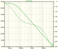
On a time scale of 300us the response is as expected. An FFT over this interval shows a -3dB bandwidth of 30kHz
and a gain of 69dB, the same values that the SPICE .AC simulation comes up with.

Here the FFT of V(out)/V(in), aka the transfer function.

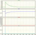
However, a 300us interval is too short to show frequencies below 3kHz, so I expanded the FFT window to 1s. The simulated time waveform now reveals an additional, superposed, exponential decay of the signal on node out.

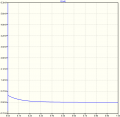
This long tail completely drowns out the short-window results an produces the FFT shown below:

The response over a 1s window is completely different from the expected one (first picture above) and suggests a much wider bandwidth and a much higher (+50dB) gain.
What happens here is that we only see the transfer function related to the impulse response shown between 300us and 1s. The 10ns input spike temporarily upsets the DC biasing of the amplifier. Because of the big capacitors it takes almost a second before this second transient dies out.
My question: Would this effect influence the subjective sound quality of this amplifier, i.e., can people hear the effects of this bias modulation?
In practice there will not be any 10ns spikes on the source material, but there might be RF noise pickup on the input when it is not explicitly filtered. Intentional spikes (be it much wider) can be in the programme source and their effect might be proportionally larger.
In the circuit below, V1 injects a 10ns wide square-pulse (Dirac impulse) into an AC-coupled 2-transistor amplifier.
On a time scale of 300us the response is as expected. An FFT over this interval shows a -3dB bandwidth of 30kHz
and a gain of 69dB, the same values that the SPICE .AC simulation comes up with.

Here the FFT of V(out)/V(in), aka the transfer function.

However, a 300us interval is too short to show frequencies below 3kHz, so I expanded the FFT window to 1s. The simulated time waveform now reveals an additional, superposed, exponential decay of the signal on node out.

This long tail completely drowns out the short-window results an produces the FFT shown below:

The response over a 1s window is completely different from the expected one (first picture above) and suggests a much wider bandwidth and a much higher (+50dB) gain.
What happens here is that we only see the transfer function related to the impulse response shown between 300us and 1s. The 10ns input spike temporarily upsets the DC biasing of the amplifier. Because of the big capacitors it takes almost a second before this second transient dies out.
My question: Would this effect influence the subjective sound quality of this amplifier, i.e., can people hear the effects of this bias modulation?
In practice there will not be any 10ns spikes on the source material, but there might be RF noise pickup on the input when it is not explicitly filtered. Intentional spikes (be it much wider) can be in the programme source and their effect might be proportionally larger.
Attachments
-
2.6 KB Views: 2
Last edited:


