Alexa Enabled Projector Screen Project

Thread Starter

Thebearman

Joined May 19, 2018
2
So I got myself one of those Alexa Echo dot thingies, a handful of MiMoo smart WiFi switches, a projector and motorised screen, you thinking what I'm thinking? Good! Cos I don't have much of a clue and could really use some help! I'm an amateur but happy to share my progress here.


The projector screen has a remote and a wired controller box with up, stop and down buttons. My thinking is to reroute the up and down buttons to two smart switches. I'm just not too confident as to where abouts to divert on the PCB.


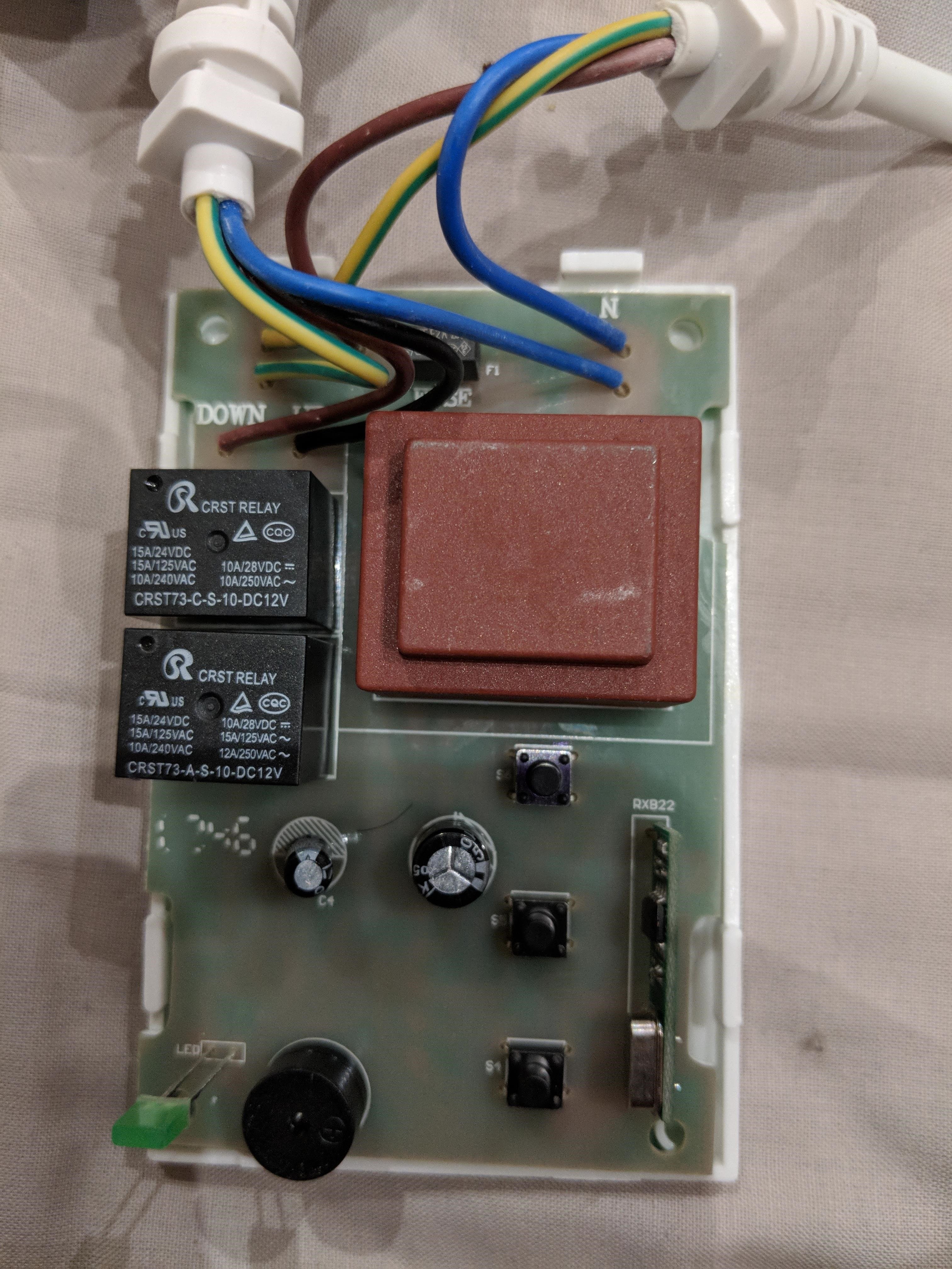
Can anyone verify that this could work, does the voltage allow? Where would be best to solder the live and neutral wires to bypass the up and down buttons?

Cheers me dears.
 

crutschow

Joined Mar 14, 2008
38,315
Would need some kind of wiring diagram for that screen controller to better advise you.

Otherwise you could use the Alexa outlet to power a 120VAC or 240VAC (as required) relay in parallel with the up button and one outlet and relay in parallel with the down button.
Does the screen automatically stop at the top and bottom?

If you wanted to have it work like a garage-door opener using just one outlet, you would need to add some additional circuitry with a flip-flop to alternate directions for each actuation of the outlet.
Have you had any experience wiring simple electronic circuits?
 

Thread Starter

Thebearman

Joined May 19, 2018
2
Hey Crutschow,

Thanks for the reply, I will do some digging to try find a diagram but doubtful. My knowledge is very basic, I've made repairs on PCBs in the past following instructions and made a few hacks with limited knowledge. Like my custom wacom Cintiq.
https://youtu.be/FrXXGgHW-C8

The screen does automatically stop at the top and bottom however ideally I would not want it to stop at the extreme on the bottom. Not a project killer but if there is some clever way around it all the better. I could maybe look at programming Alexa to only enable the down switch for a certain amount of time if possible (will look into that)

The PCB shows the locations of the three buttons. Top is up (i.e nearest wires) middle stop, bottom down. The buttons seem to have four solder points each, I'm just not sure which of those are live and neautral, i.e where I would affix the reroute to the MiMoo switch.
 

crutschow

Joined Mar 14, 2008
38,315
The buttons seem to have four solder points each, I'm just not sure which of those are live and neautral
There may be only on SPST contact with two of the pins being common on each side of the switch.
You could use an ohmmeter to determine which pins (if any) may be connected together.
You can also use the ohmmeter to determine which pins are connected together when the button is pushed.
Then you just solder the relay contact connection across those pins to let the relay (controlled by Alexa) perform the push-button function.
 
Top