You can run two regulators from the same winding, if you dont need a Negative supply then use two diodes to make a full wave this will double the current output.
You can run two regulators from the same winding, if you dont need a Negative supply then use two diodes to make a full wave this will double the current output.
Ahhh. Didn't know that. Thank you.
So, just so I'm crystal clear here, with my centre tapped secondary, just use one end & the centre?
Please forgive my ignorance, but how do you get double the current?
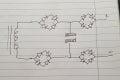
Use both Yellow wires, one to each diode Anode then join the Cathodes together like in the drawing to make the Positive supply, the Black is the Ground output.
Your Transformer will be wired like this circuit, so you could use the bridge rectifier and smoothing capacitors , you will need to drop the voltage down to 40V to input into the LM317 or LM337 , with the ideas posted. Ideally you need PnP pass transistors for extra current, or if you use LM337 you can use NpN.
You can run two regulators from the same winding, if you dont need a Negative supply then use two diodes to make a full wave this will double the current output.
This configuration will give you 40 volts DC (without the capacitors) at full wave rectification with only experiencing one diode forward voltage drop (0.6 to 0.7V typical).
Right got that. Thank you both very much. The darkness is clearing slowly ;-)
So, running it like that using just two diodes and then smoothing I calculate will deliver 56.56v. The max voltage into a LM317HV is 57v so how do I drop that voltage enough to give me a couple of volts headroom?
Thinking about things, I have 4 x 270R 5W & 2 0.1R 5W dropper resistors and I also have some large bridge rectifiers...
How about if I wired two rectifiers so they presented as two pairs to give me the initial full wave rectification? That would drop the voltage into the caps wouldn't it?
If I then put some in AFTER the caps, would that not drop the voltage too? A rough calc says that would give me something like 4v of head room? Or am I simply talking rubbish? BTW I understand this is not what one would call an elegant solution but they would easily carry the max current in this config :-Q
Just put two 1N54001 diodes in series before the regulator that will drop about 1.5V, then when you put a load on it the input voltage will drop to around 50V.
Thank you for that. So, am I right in saying that I calculated the secondary voltage for a full wave rectifier at 1.41 when I should have used 0.71?
If that's the case then normal 317s can be used.
Is there anything wrong (ignoring elegance) with using the bridge rectifiers in the configuration shown prior to the capacitor to do the recification?
Just put two 1N54001 diodes in series before the regulator that will drop about 1.5V, then when you put a load on it the input voltage will drop to around 50V.
So how does mine differ electrically (ignoring the forward volt drop of the additional diode) from the essence of DodgyDaves post 23? Ignoring the ones AFTER the cap.
My prob Dave is that I don't have any 54001s. I have what I have and would like to actually make it tomorrow ;-)
So how does mine differ electrically (ignoring the forward volt drop of the additional diode) from the essence of DodgyDaves post 23? Ignoring the ones AFTER the cap.
Ok if you haven't got 1n54001, use the bridge rectifier as the two diodes, just use the +/- terminals, + to the regulator - as the dc input, this will put 2 diodes in series and drop approx 1.5V DC.
Ok if you haven't got 1n54001, use the bridge rectifier as the two diodes, just use the +/- terminals, + to the regulator - as the dc input, this will put 2 diodes in series and drop approx 1.5V DC.
Thats why I drew them as I did . Being in parallel, they can also spread the current load. Theres no danger of burning one out as the rectifier is 3 times the maxcurrent I'll use.
Right got that. Thank you both very much. The darkness is clearing slowly ;-)
So, running it like that using just two diodes and then smoothing I calculate will deliver 56.56v. The max voltage into a LM317HV is 57v so how do I drop that voltage enough to give me a couple of volts headroom?
Thinking about things, I have 4 x 270R 5W & 2 0.1R 5W dropper resistors and I also have some large bridge rectifiers...
How about if I wired two rectifiers so they presented as two pairs to give me the initial full wave rectification? That would drop the voltage into the caps wouldn't it?
If I then put some in AFTER the caps, would that not drop the voltage too? A rough calc says that would give me something like 4v of head room? Or am I simply talking rubbish? BTW I understand this is not what one would call an elegant solution but they would easily carry the max current in this config :-Q
Aside from having to reverse the bottom two - as someone already pointed out - I really don't see the value in putting all those diodes into the circuit. Two parallel diodes will still act the same as one big diode, so you're not getting 16 forward voltage drops - you're only getting eight. In theory that'll drop about 5 and a half volts. From 56 down to 50 is still more than your 317 is rated for. Others have shown you better circuits. Why are you still trying to design your own circuit - when we've pointed out that you're not on the right track?
Since you're requiring an amp and a half (317 max continuous amperage) why not just get a better transformer. Doesn't need to be center tapped unless you want a PLUS and MINUS supply (split rails) with ground in the middle. It's a little like using a V8 engine to charge cell phones. Wasteful.
Exactly what is it you want? A 12 volt power supply? Single positive and single negative? I have plenty of 12 volt SMPS power bricks that are rated for 5 amps. I have an ATX power supply that gives me +12 to Gnd, -12 to Gnd, 5V to Gnd and 3.3V to Gnd. I think the 5 volt is like 20 amps or more. 12 volts may be 17 amps (going on memory) (could be wrong). And if I was going to build a 12 volt power supply single rail, I'd go with a 12 volt secondary output transformer and a 12 volt regulator. After smoothing caps I'd have almost 17 volts to regulate down to 12. Plenty of head room. If I wanted 12 volts with split rails (+12 volts to Gnd and -12 volts to Gnd) I'd use a 24 volt transformer with a center tap. Regulators and smoothing caps and full wave bridge rectifiers. But trying to use a 40VAC CT Txfmr? Well, if that's what you want to do - will take more work than starting with the right equipment. And I've never liked the idea of using diodes to drop the voltage.
I suspect the OP is trying to use that trafo for a PSU, because, otherwise, it could only make a good doorstop. Exaclty my case; already twenty years expecting to solve the switching prerregulators negative and positive with ICs and inductors available locally.
Meantime, the last 15 years or more, going away with this:
 Facebook
 Google
 GitHub
 Linkedin


.jpg")


