Adjusting the electrical length of antennas

MisterBill2

Joined Jan 23, 2018
27,998
WHERE that capacitance gets added is what makes the difference. Consider that the meaning of "SHUNT" is quite different from the meaning of the word "EXTENSION."
Shunt capacitance on an antenna structure will need to be between two points separated by some amount of inductance. That is not possible at an end.
This is an instance where the exact meaning of a word really affects the meaning of the statement.

So you need to visualize the antenna as a string of inductors in series, which is what the antenna simulator software does. Each of those inductors has the inductance and capacitance of a section of wire of that same length. So a shunt capacitance is in parallel with that inductance, effectively cancelling part of it. Simple in a simulator, difficult in the physical world.
 

nsaspook

Joined Aug 27, 2009
16,432
My point is that I have read quite deeply into this query but so far not found a suitable and believable answer. The prospect of doing the same with ‘100’ pages of a well used book does not inspire me for a positive outcome.

I am new to RF issues but it is my Physics training that gives the impression otherwise.
You're reading deeply for a why query but not for the basic information of what? These types of book will give you a positive outcome if you have Physics training (that gives very little information about actual electrical engineering) as you will learn the background engineering needed to understand the terms of the art of antennas. That well used book is a mater-price of great information without too much mathematical fluff.
https://en.wikipedia.org/wiki/Ronold_W._P._King
His research group at Harvard spent the 1940s and 1950s developing the theory of antenna, using the cylindrical antenna as a boundary value problem subject to Maxwell's equations. Also, scattering and diffraction of electromagnetic waves from spheres, cylinders, strips, and disks, conducted within earth, under water or in tissue.[5] King is responsible for the inverted-F antenna, the most widely used antenna in mobile phones. However, he did not develop this antenna for that purpose. Rather the intended use was missile telemetry.[6]
His book with the physics based math is this one.
1750518820086.png
 

SamR

Joined Mar 19, 2019
5,526
Quarter wavelength units typical,

500/ Frequency in MHz = Feet in length for full wavelength

Then divide it into 1/4 wave, 1/2 wave, 5/8 wave or any other fraction or even full wavelength

Then decide whether vertical or horizontal alignment,

etc., etc.,

Then, after installation, trim to minimum SWR using antenna analyzer for optimal power feed... Etc., etc.,

Actually very simple and over the last 40 years I've built many horizontally polarized wire antennas. Best bang for yer bucks! Price out a 50' tower with horizontally polarized 40/80M rotatable beam antenna and see! Just the tower guying alone will cost more...
 
Last edited:

Thread Starter

Tutor88

Joined Feb 8, 2023
306
You're reading deeply for a why query but not for the basic information of what? These types of book will give you a positive outcome if you have Physics training (that gives very little information about actual electrical engineering) as you will learn the background engineering needed to understand the terms of the art of antennas. That well used book is a mater-price of great information without too much mathematical fluff.
https://en.wikipedia.org/wiki/Ronold_W._P._King

His book with the physics based math is this one.
View attachment 351562
As a Physicist by background and a science teacher that’s just fine. My projects need that depth.
 

nsaspook

Joined Aug 27, 2009
16,432
Quarter wavelength units typical,

Wavelength in MHz/ Wavelength = Feet in length

Then divide it into 1/4 wave, 1/2 wave, 5/8 wave or any other fraction or even full wavelength

Then decide whether vertical or horizontal alignment,

etc., etc.,

Then, after installation, trim to minimum SWR for optimal power feed... Etc., etc.,

Actually very simple and over the last 40 years I've built many horizontally polarized wire antennas. Best bang for yer bucks! Price out a 50' tower with horizontally polarized 40/80M rotatable beam antenna and see! Just the tower guying alone will cost more...
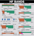
It's nice to be in the HAM world with narrow bands you are allowed to use. We used the entire spectrum (from our authorized frequency book, that skipped frequencies in the HAM bands and other important services) so most of ours were non-resonant antennas like long wires off the mast with big tuning matches or usually electrically short whips for HF on the sides of of ships. We would scan the HF band using the ionospheric sounding data we received to select likely frequencies for the next few hours for a long period HF termination (a term we used long distance HF point to point to a client).
https://apps.dtic.mil/sti/tr/pdf/ADA214996.pdf
Specification for HF Maximum Usable Frequency (MUF) Model

After finding a clean slice of spectrum on the receiver, we would fire up a test transmitter signal of a few hundred watts with a barker code on it and notify the distant end using the HF current link before it was lost.
https://en.wikipedia.org/wiki/Barker_code

After synchronization was solid, we would shift to that for the HF termination, and do the prep work for the next shift. These HF terminations could last weeks or months, with very few interruptions in service over HF paths for thousands of miles.

For something really critical, we would use up to quadruple signal diversity. High and Low HF bands with several HF links in each band all connected to the data combiner that selected the most stable data (usually).
 
Last edited:

SamR

Joined Mar 19, 2019
5,526
Hams are also using wide spectrum. I don't think you will find any of the major ham radio manufacturers NOT using Software Domain Radios and Roofing Filters. But due to FCC restrictions all Amateur radio communication must be "in the clear" so no indecipherable frequency hopping XMTRs allowed. So, with software filters we can zoom in on a signal and trim out most of the manmade noise most of the time and the same sorta goes for transmitting as well. 400Hz CW tone on a carrier can be trimmed down to ~90Hz received width where the extremely narrow crystal filter on my HW-101 was 250Hz and 3.6kHz SSB SDR roofing filter trimmed down to maybe ~1.9kHz at best depending on legibility. Even my 10-year-old ICOM IC-7410 (out of date and discontinued) has SDR Monochrome wideband scanning where the new ones have dual band color displays but limited as to transmit bandwidth and no hopping unless by "recognized and publicly tested" software modes. And lots of software modes including Morse and RTTY. Plus, with my iPhone, I have worldwide 4M and 90cm coverage piggybacking onto "6190 nodes" on installed repeaters even in countries where my communications are frowned upon by both sides. I would say that there are more ex-military Hams than in the normal population distribution and they kinda "brought the goodies" they were trained for with them.
 

nsaspook

Joined Aug 27, 2009
16,432
1750526597607.png
We used nearly everything in between ham and dedicated service bands with no power limitations. It's relative, to us, those were very narrow bands that could not support our 24/7 operations.
So, we mainly used traveling wave instead of tuned antennas and our transmission lines from the RF output of the radio match (usually 50 ohm impedance input but we had a few old 300 ohm units) to the radiating elements were nearly always reactive, with high SWR.
1750527324180.png
 
Last edited:

Thread Starter

Tutor88

Joined Feb 8, 2023
306
In the line equation, more L or C raises electrical length. But for an antenna with too much L, adding C in parallel cancels inductive reactance (XL=XCXL=XC). This restores optimal impedance, “shortening” the electrical length. It's about L and C's series - parallel setup.
Yes I agree. The key issue was essentially why does a 1/4 wave monopole antenna have too much XL in the first place that requires ‘cancelling’ with extra capacitance (XC). It seems to be due to ‘end effects’ in antennas and probably also the fact that the speed of propagation in the antenna is slower than in free space. If not directly involved that seems to be tangentially.
 
Top