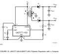
Adjustable power supply with inverting and noninverting outputs using regulator IC MC34063

Thread Starter

Shamoooot

Joined Apr 3, 2023
27
Hello

I am looking for recommendations for a DC-DC power regulator IC for a power supply with the following specs:

- Built in current limiting function
- Not very tiny and can be easily soldered with common tools

Can be used for inverting output: -18 V to -1.25/0
Can be used for non-inverting output: 0/1.25 to 18 V
Current limit: around 1A

I am thinking of MC34063, but I would like to see some opinions and suggestions.

Thanks
 

Thread Starter

Shamoooot

Joined Apr 3, 2023
27
Thank you Pyrex, this is a really good option especially with the adjustable current limit, however I can't see that it can be used for negative (inverting) output.

Or is it possible?.
 

crutschow

Joined Mar 14, 2008
34,918
I can't see that it can be used for negative (inverting) output.
No, but you can use a negative DC input for the regulator with the positive side grounded and the regulator common becoming the negative output
From the regulator's point-of-view and to the outside world, it makes no difference which output terminal is considered "ground".

What source are you planning to use for the regulator's DC input?
 

Ian0

Joined Aug 7, 2020
10,293
Thank you Pyrex, this is a really good option especially with the adjustable current limit, however I can't see that it can be used for negative (inverting) output.

Or is it possible?.
Look at the MC34063's ancestor, the LM78S40.
Because of its antiquity it's not very quick and not very efficient by modern standards, but it's very good for teaching the principles involved.
 

Thread Starter

Shamoooot

Joined Apr 3, 2023
27
No, but you can use a negative DC input for the regulator with the positive side grounded and the regulator common becoming the negative output
From the regulator's point-of-view and to the outside world, it makes no difference which output terminal is considered "ground".

What source are you planning to use for the regulator's DC input?
Thank you, could you please share an example circuit. After some searching I think the LM2596 might be the best alternative, but I am still struggling with the circuit topology to make it negative adjustable output.

The source will be the filtered output of a bridge rectifier.
 

crutschow

Joined Mar 14, 2008
34,918
The source will be the filtered output of a bridge rectifier.
You would need to change that to one with both a positive and negative output to common.
This could be done with a bridge rectifier connected to a center-tap output transformer (center-tap to common) of a transformer with the appropriate current and voltage rating.
The bridge then acts like two full-wave rectifiers for the positive and negative voltages.
Is that feasible for you?
 

Thread Starter

Shamoooot

Joined Apr 3, 2023
27
You would need to change that to one with both a positive and negative output to common.
This could be done with a bridge rectifier connected to a center-tap output transformer (center-tap to common) of a transformer with the appropriate current and voltage rating.
The bridge then acts like two full-wave rectifiers for the positive and negative voltages.
Is that feasible for you?
Yes indeed, as long as I can control outputs separately it would be fine.
 

ronsimpson

Joined Oct 7, 2019
3,263
What you are asking for is hard to do.
Here is an example that could take 24V to +/-12V for example. By adjusting R1,2 you can set the voltage.
Right now it only regulates +Vout not -Vout.
1708876390302.png
 

crutschow

Joined Mar 14, 2008
34,918
I was thinking 24V input, but I still didn't get the transformer
What don't you get?
If you want 24Vdc from the rectifiers, then you would need a transformer with a center-tapped output of about 36Vac.
Its RMS current rating should be at least 1.5 times the maximum DC input current to the regulators.

For 1A @ 18Vdc from the regulators the 24Vdc input current will be about 0.8A with a 90% regulator efficiency.
The transformer rating should then be 1.2Arms @ 36Vac (center-tapped).
 

Thread Starter

Shamoooot

Joined Apr 3, 2023
27
What don't you get?
If you want 24Vdc from the rectifiers, then you would need a transformer with a center-tapped output of about 36Vac.
Its RMS current rating should be at least 1.5 times the maximum DC input current to the regulators.

For 1A @ 18Vdc from the regulators the 24Vdc input current will be about 0.8A with a 90% regulator efficiency.
The transformer rating should then be 1.2Arms @ 36Vac (center-tapped).
I meant I still didn't buy the transfomer yet, so I have space in choosing whatever value required.

Now regarding your suggestion I fully understand what you mean, but what is this IC that can do the job (two outputs, inverting/non-inverting, while both can be separately adjustable, and last but not least can be current limited).

If you can find such a circuit I would appreciate if you can please share it.
 

Thread Starter

Shamoooot

Joined Apr 3, 2023
27
Thank you again..
Yes, I will focus on LM2596 and make two separate circuits, but as I mentioned before I am still struggling to find the circuit topology for the adjustable inverting output..
 
Last edited:

crutschow

Joined Mar 14, 2008
34,918
That's not what he wants.
what is this IC that can do the job (two outputs, inverting/non-inverting, while both can be separately adjustable, and last but not least can be current limited).
 

Thread Starter

Shamoooot

Joined Apr 3, 2023
27
So using a plus and minus voltage source as I discussed is not an option?
Or do you not understand what I said?
I believe I did understood you, however we were talking about the input up to the regulator IC. No issues with using center tapped transformer etc..

Now for the non-inverting output it's fine as it's already found online, however the circuit for the adjustable inverting output is no where to be found.

1708961687343.png

I can find the circuit for constant negative voltage but not adjustable!.

1708961636531.png
 

Ian0

Joined Aug 7, 2020
10,293
I believe I did understood you, however we were talking about the input up to the regulator IC. No issues with using center tapped transformer etc..

Now for the non-inverting output it's fine as it's already found online, however the circuit for the adjustable inverting output is no where to be found.

View attachment 316236

I can find the circuit for constant negative voltage but not adjustable!.

View attachment 316235
Haven’t you noticed they are both the same circuit, just with the power supply connections rearranged?
 
Top