AD623 Instrumentation Amplifier gain stuck at 2

ebp

Joined Feb 8, 2018
2,332
The voltage divider for the input bias must be decoupled. Those high value resistors will produce considerable Johnson (Nyquist) noise and may also be producing additional noise, depending on the type. They should not be carbon film. There is a buffered supply midpoint voltage available from at U2.1. Is there any reason not to use that for biasing the input buffers? Each could be biased directly with a single resistor, which would remove the gross impedance imbalance at the inputs that exists in the circuit as it is.

I would test with the IA output reference driven by a fixed DC voltage rather than the integrator until everything else is confirmed to work properly.
 

Thread Starter

Hamed P.Azad

Joined Jun 25, 2017
17
hi,
Thank you for that brief explanation.
Thinking about how your electrodes [ SG pins ] will be electrically biassed, with reference to the bodies common/ground electrode, due to the input resistor network potential divider, surely they will 'inject' a potential difference between to electrode points and ground?
Will this be a problem.?
E
This is actually a very important problem. Yes, there is actually some potential difference (in my experience it is negative) injected to the system. But there are some points to that, first of all the electrodes have very high impedance (normal electrodes have 2M ohms and they go up to 18M ohms in some applications) so there's micro-ampers current, second of all the integrating feedback on REF pin deals with that pretty well.
 

Thread Starter

Hamed P.Azad

Joined Jun 25, 2017
17
The voltage divider for the input bias must be decoupled. Those high value resistors will produce considerable Johnson (Nyquist) noise and may also be producing additional noise, depending on the type. They should not be carbon film. There is a buffered supply midpoint voltage available from at U2.1.
The resistors are 603 SMD 1% resistors, so I don't think they are carbon film. But I don't really understand Nyquist noise you mentioned. The input resistor is in Mohms and I'm not sure connecting a low impedance node (opamp output) would be a good idea.

I would test with the IA output reference driven by a fixed DC voltage rather than the integrator until everything else is confirmed to work properly.
This is not important. I actually did test with fixed REF before, but it's not different.
 

ebp

Joined Feb 8, 2018
2,332
1% 0603 resistors can be either thick or thin film. Both have the same Johnson-Nyquist noise, but thin film can be as much as 100 times lower current noise.
All resistors produce Johnson-Nyquist noise, simply because they are resistors. If you do a web search on johnson noise you should find lots of info. I suspect the resistors are a source of at least some of the noise you see with the inputs shorted.

You would still bias your inputs through resistors, but each input would go through a resistor to the output of the U2. By doing this, each input would have the same impedance. The way it is now, the upper input is biased through 3 megohms (2M to thevenin equivalent of 1M), whereas the lower input is biased through the additional 2M of the source. If you stick with the resistive divider you could simply bias each input with a 2M resistor from the midpoint of the divider across the supply. If you add a decoupling capacitor to the midpoint of the divider across the supply that node will approach zero AC impedance, depending on the value of the capacitor, but the resistance is unchanged. Maintaining balanced everything at the inputs to an instrumentation amplifier is critical to achieving good common mode rejection.
 

Thread Starter

Hamed P.Azad

Joined Jun 25, 2017
17
1% 0603 resistors can be either thick or thin film. Both have the same Johnson-Nyquist noise, but thin film can be as much as 100 times lower current noise.
All resistors produce Johnson-Nyquist noise, simply because they are resistors. If you do a web search on johnson noise you should find lots of info. I suspect the resistors are a source of at least some of the noise you see with the inputs shorted.

You would still bias your inputs through resistors, but each input would go through a resistor to the output of the U2. By doing this, each input would have the same impedance. The way it is now, the upper input is biased through 3 megohms (2M to thevenin equivalent of 1M), whereas the lower input is biased through the additional 2M of the source. If you stick with the resistive divider you could simply bias each input with a 2M resistor from the midpoint of the divider across the supply. If you add a decoupling capacitor to the midpoint of the divider across the supply that node will approach zero AC impedance, depending on the value of the capacitor, but the resistance is unchanged. Maintaining balanced everything at the inputs to an instrumentation amplifier is critical to achieving good common mode rejection.
You made some good points here. I'm not sure about the type of my resistors. Also a good point about johnson noise. Never considered that.

It would also worth investing a little time on changing input bias. I never was comfortable with resistor division, but it was a solution I found. Just to clarify though, do you think it's better to use one opamp for EACH input (and isolate voltage division), or I can use one opamp for both inputs?

Since I don't have any AC signal in my supply, is it good to consider capacitors?
 

ebp

Joined Feb 8, 2018
2,332
I think you should be fine with using a single op amp to bias both inputs. This has the advantage that any residual noise at the op amp output, which should be pretty minimal if its input is well filtered, is coupled equally to both IA inputs and therefore cancelled by the common mode rejection of the IA.

In some biopotential measuring circuits a "ground" connection electrode is used (e.g. EKG leg electrode). Where a single supply amplifier system is employed the "ground" can actually be a driven voltage with respect to the amplifier circuit common. Using the output of U2, as you have it configured, would be typical. With this arrangement it is usually not necessary to bias the amplifier inputs directly, since both are now referred to the the driven electrode which provides both voltage biasing and a path for the input bias current of the amp itself. By eliminating the need for bias resistors you can gain the full benefit of the ultra-high input resistance of the amplifiers. Of course this may not be compatible with your overall system (e.g. other grounds for other instruments, electrocautery, etc.). When the amp inputs are open circuit and have no place for their bias current to go the output will be unpredictable.

Even with a battery as the supply, high-frequency decoupling capacitors and even "bulk" capacitors, often tantalum, are good practice. They help prevent problems such as unintended feedback/feedforward/crosstalk due to greater-than-zero supply impedance which includes the battery itself and connection resistance and inductance. In sensitive circuits it often doesn't take much to make a mess of things.

It might be worth considering one of the charge pump voltage inverters to produce a negative rail for your amplifiers. Care is required to avoid introducing noise, but a simple LC filter can work quite well. Just beware that really "good" inductors and capacitors can produce a very sharp resonance which can be detrimental. This can be tamed with either an inductor with a little resistance or a small discrete resistance. It is interesting to play with simulation of the filter to see the effect of damping due to resistance.
 

Thread Starter

Hamed P.Azad

Joined Jun 25, 2017
17
It is interesting to play with simulation of the filter to see the effect of damping due to resistance.
Thank you for this advice. I think I may be able to work with this to find a good design. Just a question. I chose TPS60401 as my charge pump inverter since it only requires 3 capacitors to work. But as datasheet demonstrates, the output ripple is quite high (about 100mV in figure 25). I'm pretty sure this is not good, and I need to use an LC filter. But I can't find any simulation software that contains this, or any other similar IC. I have TINA installed on my laptop, and I can have access to cadence OrCAD schematics. But none of these two has such libraries. I also could not find the .lib or .cir file to import the spice design. Can you help me?

P.S: I can design LC filter alone, but it would be better to simulate with the IC itself.
 

ericgibbs

Joined Jan 29, 2010
21,517
Hi Hamed,
I would never use a switcher power supply on a project that is processing very low level signals.
You can add filtering, but there is always some level of switching noise present on the supply.
E
 

Thread Starter

Hamed P.Azad

Joined Jun 25, 2017
17
Hi Hamed,
I would never use a switcher power supply on a project that is processing very low level signals.
You can add filtering, but there is always some level of switching noise present on the supply.
E
Thank you for your concern Eric. Yes, I am worried about that as well. Back when I used two regulators to provide negative supplies, this switching noise was clearly present in my signal. To sum up, I started with single supply and regulators to provide negative supply, then I moved to 2 batteries, then I moved to single supply. Now it would be nice if I could again provide negative supply.

The thing I'm most concerned about is that LC filter is unable to remove the switching noise very well. In the datasheet, it is stated that TPS60401 produces a 20KHz ripple, so I'm thinking of applying a 1KHz LC lowpass filter that reaches -30dB in 20KHz. What do you think about this?

H
 

ericgibbs

Joined Jan 29, 2010
21,517
hi,
Have you considered using a 7.4v battery and creating a virtual ground around +/-3.7V, using a OPA .?
I will look at LTSpice, see if it is possible to simulate a pseudo 20kHz ripple into a 1kHz LPF, will post back results.
E
 

Thread Starter

Hamed P.Azad

Joined Jun 25, 2017
17
hi,
Have you considered using a 7.4v battery and creating a virtual ground around +/-3.7V, using a OPA .?
Two problems come to mind with this solution.
1. 7.4V batteries are not standard, small, rechargeable Li-ion batteries. I think these batteries may be bulkier than my current design.
2. Creating a virtual ground result in a voltage difference between REAL Ground and the ground applied to ICs. The problem is charging the batteries while the system is on. I don't know why, but InAmps (they were AD620 then) didn't work right each time the device was turned on while being charged.

I used 2 batteries in series, and connected the mid-point ad the ground, thus resulting in negative and positive rail.

Edit:

Simulating the filter results in a ripple of roughly 1.5mV p. Do you think this actually happens with TPS60401?

Untitled.jpg
 
Last edited:

Thread Starter

Hamed P.Azad

Joined Jun 25, 2017
17
hi,
OK,
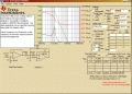
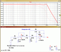
These are the preliminary results using the Texas filter Pro [free download] and LTSpice.
Thanks,
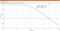
I don't have the option to use an opamp filter. I was thinking to do this with a simple LC filter. the picture attached shows my filter frequency response. I think it's good enough, at least in theory it looks sufficient.

What are the dimensions of the final enclosure.?
The PCB I designed now is 29X26 mm. However, I'm seeking smaller sizes. It should be light and small to be mounted straight on animal's head.
 

Attachments

ericgibbs

Joined Jan 29, 2010
21,517
hi H,
Wow, that is a small available volume for building your project using off the shelf components, including the battery.
I don't know the species of animal that it will be used on, but is it possible to also place a collar on the animals neck, [ dog for example] that holds the battery pack.?
E
 

Thread Starter

Hamed P.Azad

Joined Jun 25, 2017
17
hi H,
Wow, that is a small available volume for building your project using off the shelf components, including the battery.
I don't know the species of animal that it will be used on, but is it possible to also place a collar on the animals neck, [ dog for example] that holds the battery pack.?
E
Well, this is just the headstage. Sorry for missing this point. The filters and gain are in a separate package. Although the headstage should be in this size with the battery, and maybe like 1cm thick.

Animals are mostly rats and small monkeys.
 

ericgibbs

Joined Jan 29, 2010
21,517
hi,
I see from your response plot that the Gain is ~29dB down at 20kHz.

I am trying to visualise what the completed project would look like, where the the modules are located relative to each other, is it possible to post a simple block diagram of the complete project.?

E
 

ebp

Joined Feb 8, 2018
2,332
Why not use the version of the converter that runs at 50 kHz or 250 kHz? I haven't looked carefully at the datasheet, but I presume the higher frequency part is somewhat less efficient. Power supply rejection of the amplifiers will be lower at higher frequency, so there is a tradeoff that must be evaluated depending on how you expect power supply noise to enter the signal path.

Note that the output ripple oscillographs in the datasheet are at 30 mA. That is a lot of current, and probably an order of magnitude more than your circuit will require. Ripple will be reduced at lower current.

When I was analyzing noise for such a converter (I don't remember what I used), I simply built a model using controlled switches, each with a resistor in series. This gave me freedom to investigate the effects of actual switch ON resistance. I did the same for the capacitors to investigate the effects of ESR. It is interesting to play with the ESR of the flying capacitor.
Using the charge pump improved the circuit performance by eliminating the need to bias an amplifier input from a precision voltage reference and the noise associated with the reference, which was very hard to filter. The circuit was an amplifier for a sensor that produced ultra low level output for the signal of interest.

You must be very careful with circuit layout to keep the currents associated with the charge pump local and out of signal grounds and to minimize loop areas to avoid radiation. Ripple current at the input of the pump must also be considered.

The filter response shown at #34 is only first order (20 dB per decade), so whatever it is, it isn't LC.
 
Top