AC120v to 60VDC at 3AMP circuit blew up, not sure why

Status
Not open for further replies.

Thread Starter

Cyclicz

Joined Apr 17, 2017
62
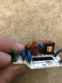
My circuit consists of a 120VAC to 60vdc (3AMP) switched converter which goes through a couple parallel LEDs and finally through a N channel mosfet (triggered with a pwm signal.) I plugged it in and it worked for a couple of seconds but then a click was heard and now it fails to chooch. I was wondering if any of you knew of any negative effects one of these mosfets might have on such a converter. I'll provide a full schematic once I'm done reverse engineering the circuit, but I'm quite baffled at this point.
 

Sensacell

Joined Jun 19, 2012
3,432
Does your circuit have a current limiting resistor or regulator?

Connecting LED's direct to a voltage source will cause uncontrolled current flow - (smoke)
 

Thread Starter

Cyclicz

Joined Apr 17, 2017
62
Halfway done with mapping the circuit board into a schematic, its starting to look like it's a buck converter with rectifiers and centered around a AL1696 type constant current converter. This is a circuit from the schematic of the AL1696, not sure if I can locate the source of the issue of placing a NPN MOSFET inbetween the smoothing capacitor and the ground path of the LEDS.
 

Attachments

ian field

Joined Oct 27, 2012
6,536
This circuit came out of an LED lightbulb so I definitely assume so.
Tread carefully - its probably a transformerless supply and not allowed by the forum T&C.

LED bulbs can be found very cheap and probably not worth attempting repair.

The *REALLY* cheap ones use a different regulator which is especially not allowed here.
 

Dodgydave

Joined Jun 22, 2012
11,285
Halfway done with mapping the circuit board into a schematic, its starting to look like it's a buck converter with rectifiers and centered around a AL1696 type constant current converter. This is a circuit from the schematic of the AL1696, not sure if I can locate the source of the issue of placing a NPN MOSFET inbetween the smoothing capacitor and the ground path of the LEDS.
Have a look at the datasheet, current sense pin3, with a resistor R5,there are two applications modes for it..

https://www.google.co.uk/url?sa=t&s...gghMAA&usg=AFQjCNHi5HNIVLFogCwTUpm7_73FECAlvA
 
Last edited:

Thread Starter

Cyclicz

Joined Apr 17, 2017
62
Tread carefully - its probably a transformerless supply and not allowed by the forum T&C.

LED bulbs can be found very cheap and probably not worth attempting repair.

The *REALLY* cheap ones use a different regulator which is especially not allowed here.
Technically it has a transformer but I only see three pins, two of which look conndcted. Does that make it more of an inductor? If it's against the T&C along with things like Railguns this must not be very safe at all and I should probabally rethink the project if that's what I'm dealing with. Photos attached.
 

Attachments

Last edited:
Status
Not open for further replies.
Top