Facebook
 Google
 GitHub
 Linkedin
Hello
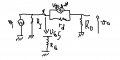
evryone please could you help me drawing AC equivalent of this configuration and simplify it , and fin Z(in) and Z(out) (input and output impedance )
evryone please could you help me drawing AC equivalent of this configuration and simplify it , and fin Z(in) and Z(out) (input and output impedance )
Attachments
-
 47.1 KB Views: 26