 Facebook
 Google
 GitHub
 Linkedin
Hello!
There is a relatively high frequency signal that should be decided whether its area under the curve exceeds a certain value or not. This will be done by by an FPGA fter digitization. At different threshold levels the FPGA will give different instructions to other equipment.
The problem is that since the frequency of the signal is quite high, this would require a relatively fast ADC, but since several pieces are required, this would increase the costs. So, as an alternative solution, it would be possible to take the absolute value of the signal, integrate it and digitize the integrated pulse only with a much slower and cheaper ADC.
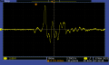
The signals are something like this, there is a deviation in the amplitude (the maximum is perhaps around 10V, I have not seen anything higher), but the frequency is something like in the picture.
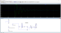
I used this circuit: Link
I simulated it in LTSpice, but the absolute value I get on the left side of R6 doesn't look exactly as it should, it even goes negative.
What should I change on the circuit to make it work normally? I guess this issue comes from the high frequency. Bonus question: at the right side, how should the value of R and C be chosen for the integrator to be suitable for such a fast signal? At least tenths of a second pass between the pulses, so they do not follow each other too quickly.
Thanks for the help!
There is a relatively high frequency signal that should be decided whether its area under the curve exceeds a certain value or not. This will be done by by an FPGA fter digitization. At different threshold levels the FPGA will give different instructions to other equipment.
The problem is that since the frequency of the signal is quite high, this would require a relatively fast ADC, but since several pieces are required, this would increase the costs. So, as an alternative solution, it would be possible to take the absolute value of the signal, integrate it and digitize the integrated pulse only with a much slower and cheaper ADC.
The signals are something like this, there is a deviation in the amplitude (the maximum is perhaps around 10V, I have not seen anything higher), but the frequency is something like in the picture.
I used this circuit: Link
I simulated it in LTSpice, but the absolute value I get on the left side of R6 doesn't look exactly as it should, it even goes negative.
What should I change on the circuit to make it work normally? I guess this issue comes from the high frequency. Bonus question: at the right side, how should the value of R and C be chosen for the integrator to be suitable for such a fast signal? At least tenths of a second pass between the pulses, so they do not follow each other too quickly.
Thanks for the help!
Attachments
-
 10.4 KB Views: 24
 -
 58.3 KB Views: 27
 -
3.1 KB Views: 10


