[About] SN74LS47N to 7 segment

Thread Starter

kemz

Joined Jul 26, 2010
3
Ok, so this is my first post since I'm new to this forum and new to electronics.

(tried the search and unfortunately ddnt find something to help with my prob)

I have a homework-activity on Computer Interfacing subject. And my problem is connecting, not really connecting but lighting-up my seven segment though a SN74LS47N IC. I'm pretty sure I connected the IC-to-7segment right, when I tested my seven segment using a multi-tester, it lits up which means it's OK and functioning. I also tested my SN74LS47N to check if it's functioning but it's ok also. I just dunno why it won't lit up when I put the things together.

My supply is roughly 5v (from a parallel port), if I'm not mistaken. And no, my parallel port is not the prob since I use it to test our previous activity and it worked fine.

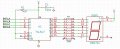
Here is my schematic diagram,


I already asked a friend and told him bout my materials but wasn't able to show him my schematic. He says it could be my resistors.

Am I using the right resistors? or I got the wrong ones?

Since 7 segment is also are LEDs put together, how come my previous activity worked fine using same resistors connected to an individual LEDs?

I need some enlightenment.. please help tnx


EDIT: forgot to label the Vcc of the IC. It's also 5v.
 

Papabravo

Joined Feb 24, 2006
22,111
You don't want a resistor in the VCC lead of the IC. Wherever did you come up with that quaint notion? You also need to connect the other inputs to a logic high or a logic low. Read the datasheet to find out which way they need to go.
 

Thread Starter

kemz

Joined Jul 26, 2010
3
You don't want a resistor in the VCC lead of the IC. Wherever did you come up with that quaint notion? You also need to connect the other inputs to a logic high or a logic low. Read the datasheet to find out which way they need to go.
So, aside from removing the resistor on the IC's vcc, is there something I should remove or they're already in right places.

About the IC inputs, I can manipulate the output of the parallel port pins to whether they be on logic high or logic low (1s and 0s) using a software on the computer.

For more info sir, what I am trying to do is manipulating the hardware using a computer software ( ie. turbo C, Visual C, etc). So my IC inputs was never an issue.

Tnx for the repz,
 

Papabravo

Joined Feb 24, 2006
22,111
OK. It is just that your schematic does not show anything connected to LT-bar(Lamp Test - turns all segments on), and BI-bar/RBO-bar, and RBI-bar. These are inputs and outputs used in multi digit displays to blank leading zeros.
 

beenthere

Joined Apr 20, 2004
15,819
There is still a problem. That one resistor in the common anode line is incorrect. It must be tied directly to the 5 volt source. But there must be individual 330 ohm resistors in the segment lines between the 74LS47 outputs and the display.

Since you are dealing with TTL, any input that is pulled up should have a resistor between that pin and Vcc. For 74LSxx, something on the order of 10K is good.

Use "74ls47" as the term in a search engine to obtain a data sheet for the IC.
 

Thread Starter

kemz

Joined Jul 26, 2010
3
OK. It is just that your schematic does not show anything connected to LT-bar(Lamp Test - turns all segments on), and BI-bar/RBO-bar, and RBI-bar. These are inputs and outputs used in multi digit displays to blank leading zeros.
Thnx for the reply, I really appreciated it and gave me infos about what does other pins do. I mean sometimes it's better ppl tell you directly what it does rather than sitting around reading some datasheets/textbooks and later on while reading you get to ask yourself again..

Nweiz, atm I'm not using that pin(s) yet cause my goal for now is just to lit up a single seven segment and just be able to produce a display of 0 to 9. (if that's what you mean on your post)

There is still a problem. That one resistor in the common anode line is incorrect. It must be tied directly to the 5 volt source. But there must be individual 330 ohm resistors in the segment lines between the 74LS47 outputs and the display.

Since you are dealing with TTL, any input that is pulled up should have a resistor between that pin and Vcc. For 74LSxx, something on the order of 10K is good.

Use "74ls47" as the term in a search engine to obtain a data sheet for the IC.
My problem is solved now, and tnx to mr.beenthere... lol funny that I ddnt thought that my resistor was resisting some of my 5v, so when I tried removing my resistors it then lit up brightly =)

I did a little curiousity test thingy and found out that my seven segment was actually lighting up already with the schematic above but when with the resistor on the common anode it just faintly lit, needed to close the lights on my room to see.


So yea, tnx for the help. It was a very big help for me. Nice community and a lot of active forumers/members. I might hang out for a while here. :D
 

n1ist

Joined Mar 8, 2009
189
If you look at the data sheet for the 74LS47 http://focus.ti.com/lit/ds/symlink/sn74ls47.pdf they have a truth table that describes the functioning of the part. According to it, RBI* and LT* must be high for normal operation, and BI*/RBO* must either be high or open. For TTL, unconnected inputs float high, but I would not count on it. I would add a pullup resistor from RBI* and LT* to Vcc. BI*/RBO* is a special case on this chip; I would leave it open. For CMOS logic, never leave any inputs floating.

/mike
 

Attachments

Top