I think all of this has been covered, but I will summarize: The driver you bought is designed to put a constant 300 mA through one to 3 LEDs in series. These LEDs must be rated at 300mA each. Thus it is not the right thing for your LEDs.
The best way to drive your 6 30mA LEDs is to use s 12V fixed voltage , make 2 strings of 3 LEDs each with a 100 Ohm resistor in each string.
I understand. Given my space requirements, I think a 240v to USB power supply would be better, using a 5v fixed voltage. But that is a minor alteration. Thank you all for your time and expertise. Perhaps I will buy some 300mA LEDs to experiment with seperately.
Do the math. 30mA x 680 ohms= 20.4 plus 3V for the LED then you need a supply of 23.4V, not 12V.
Most 5mm LEDs have a 30mA maximum momentary current rating but all the spec's are at 20mA continuous current.
There are so many LED calculators on the web it is hardly needed - but we have V/I = R, which would be 2/0.3 = 66 ohms with a 5v supply and 3v LED. Which is an unusual resistance. I have some 120 ohm resistors.
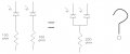
I note that someone said earlier that the same LEDs might not all take the same current if they are connected in parallel. Does that mean that I cannot connect two LEDs to one resistor, as in the schematic below? I just put resistor values in for illustration - for 5v they would obviously be different. Now I come to think of it, perhaps I have got that wrong and the resistor ought to be HALF the original value rather than TWICE, to allow double the current through?
If you did connect them in parallel, yes, the resistor would need to be 50R, not 200R. There is twice the current through the resistor, so to keep the same voltage drop, it needs to be half the resistance.
But there is a good chance that LEDs will not share current evenly. Often, devices do have LEDs in parallel, but they do need to be fairly well matched. Especially if you are running them close to the max current.
Resistors are cheap. One resistor for a series string of LEDs is ok, otherwise one resistor for each LED is recommended.
Thanks. It was just a matter of what components I had to hand, and I do not have very many small resistor values. Since you all showed me what I was doing wrong with a constant-current driver, I have taken the insides out of a mains USB charger to obtain a 5v supply - the advantage of this is that it is physically very small, but 5v is not an ideal supply for a 3v LED without some very low-value resistors.... still, it should work with a PWM dimmer, which the original driver wouldn't.....
The PWM dimmer should not drive the mains input to the 5V supply if that is what you mean.
There are a lot of PWM LED dimmer circuits on line.
Here is the first I found.. https://www.gadgetronicx.com/pwm-led-dimmer-circuit-ic555/
This is running on 9V, but the same sort of thing applies to the 5V one.
You could use an Arduino to drive it too. Have you played with them?
Oh, I just noticed the time.
I'm off to bed.
I was expecting to PWM the output from the USB supply - and probably use a Chinese component board, which is simpler than making one up myself. Though thanks for that circuit reference - if I need to fit things in a small space I have quite a few 555s...
What is 0.3? You said the LEDs are 30mA which is 0.03A. Then the resistor is 2V/0.03A= 66 ohms. Use the standard value of 68 ohms, but I think 30mA is too high.
I note that someone said earlier that the same LEDs might not all take the same current if they are connected in parallel. Does that mean that I cannot connect two LEDs to one resistor, as in the schematic below? I just put resistor values in for illustration - for 5v they would obviously be different. Now I come to think of it, perhaps I have got that wrong and the resistor ought to be HALF the original value rather than TWICE, to allow double the current through?
Each LED might have a slightly different forward voltage then the lowest voltage LED will use more current than the remaining LEDs and be brighter and burn out sooner. I never operate an LED at its Absolute Maximum Allowed Current, I always calculate ordinary LEDs to use 10mA or 20mA. I put in parallel twenty Name Brand LEDs that I bought at the same time and they work fine. I have a cheap flashlight that has 24 ordinary LEDs all in parallel and they are fine but they operate at 10mA each.
Two LEDs in parallel can use double the current of one LED then of course the resistor value is half.