A Full wave precision rectifier query

Thread Starter

trytolearn

Joined Mar 1, 2008
33
Hi, everyone

I am currently working on a autoguilded vechile project,
i am doing the inductive sensor at the min.

I am having some difficulties on the precision rectifier which i am going to use,

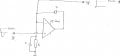
I have found this on the web
http://sound.westhost.com/appnotes/an001.htm


When I was testing this on a veroboard, I found that it gave a full wave output when
I supplied it with a +5V on V+ and -5V on the Ground. (PS, I am using a LM324 amplifier).

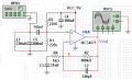
However, for my project, the power supply for this precision rectifier is aprox
0- 5 V, therefore, only positive half of the wave would be displayed.

So is there any modification i could do in order to produces a full wave rectification with a 0-5 V voltage supply ?

Many thanks
Regards

trytolearn
 

scubasteve_911

Joined Dec 27, 2007
1,203
Hi,

This is a standard issue precision rectifier, which I have built and used in the past. I am not positive, but I think you can adapt it for 0-5V operation. Clearly, you have to respect the rails of your opamp though.

If I were to try to modify this circuit, I would first bias the incoming AC with some DC. So, you would use an input capacitor large enough not to attenuate the range of frequencies you wish to use. Then, use a voltage divider set at 50/50 to the output of your capacitor. I would change all of the non-inverting inputs to a 2.5V reference voltage. I'm really not sure if this will work though because of the diodes in the first opamp. I'm sure someone will mention if there is a problem with my suggestion. It really doesn't hurt to try it anyways.

If you end up using a bipolar supply for this, then I suggest using a 5k resistor from the first non-inverting amp's input to ground and a 12k to ground for the second one.

The matching of resistors is critical for this to work, otherwise you will have really funky looking waveforms. You should understand that the first opamp is simply a precision half-wave rectifier circuit. Then, it's output is summed with the original signal. The summation for the output of the half-wave rectifier must be twice the amount of the input peak, which is why it is a 10k input resistor. Also, please note that this circuit will work poorly at high frequencies. Typically, you use fast schottky diodes and a fast opamp. Typically, the range of operation is 0<fT/100(opamp).

Steve
 

Audioguru

Joined Dec 20, 2007
11,248
The output of the first opamp goes negative. So usually the circuit uses a bipolar supply.

The old LM324 is not rail-to-rail so its max output voltage is about 1.3V less than its positive supply voltage if its load current is very low.
So if you have only a single 5V supply and you bias the opamps at +2.5V so they can swing positive and negative then the positive swing is only 1.2V.
 

Thread Starter

trytolearn

Joined Mar 1, 2008
33
The output of the first opamp goes negative. So usually the circuit uses a bipolar supply.

The old LM324 is not rail-to-rail so its max output voltage is about 1.3V less than its positive supply voltage if its load current is very low.
So if you have only a single 5V supply and you bias the opamps at +2.5V so they can swing positive and negative then the positive swing is only 1.2V.
If i am using something like this.


the non inverting input has a really high input impedance, would it causes any problem?
Which of the circuits is the best for my specification in this page?
http://sound.westhost.com/appnotes/an001.htm

Thanks
 

Thread Starter

trytolearn

Joined Mar 1, 2008
33
Hi,

This is a standard issue precision rectifier, which I have built and used in the past. I am not positive, but I think you can adapt it for 0-5V operation. Clearly, you have to respect the rails of your opamp though.

If I were to try to modify this circuit, I would first bias the incoming AC with some DC. So, you would use an input capacitor large enough not to attenuate the range of frequencies you wish to use. Then, use a voltage divider set at 50/50 to the output of your capacitor. I would change all of the non-inverting inputs to a 2.5V reference voltage. I'm really not sure if this will work though because of the diodes in the first opamp. I'm sure someone will mention if there is a problem with my suggestion. It really doesn't hurt to try it anyways.

If you end up using a bipolar supply for this, then I suggest using a 5k resistor from the first non-inverting amp's input to ground and a 12k to ground for the second one.

The matching of resistors is critical for this to work, otherwise you will have really funky looking waveforms. You should understand that the first opamp is simply a precision half-wave rectifier circuit. Then, it's output is summed with the original signal. The summation for the output of the half-wave rectifier must be twice the amount of the input peak, which is why it is a 10k input resistor. Also, please note that this circuit will work poorly at high frequencies. Typically, you use fast schottky diodes and a fast opamp. Typically, the range of operation is 0<fT/100(opamp).

Steve
HI steve

Thanks very much for your reply.

I will try it next week.
The input frequencies is only 10khz , which is within the operation range.

From this, I just realized one more problem with the overall power supply.

I have a 9.6V rechargeable battery and I believe my teammates are using a voltage divider to make a 5V supply for their motor control and PIC control. (maybe my part as well.)

My rectifier and smoothed output have to be a minimum of 4.5 V in order to be detected by the PIC control.

From Audioguru’s advices, it seems impossible to give a 4.5 V output with just a single supply.


Many thanks.

trytolearn
 

scubasteve_911

Joined Dec 27, 2007
1,203
You are welcome! You might want to follow Audioguru's advice and use a better opamp, since the output rails are terrible.. You may want to bias it at 1.75V since the output rails seem to go from ~0 to 3.5V. You're also right on the maximum frequency of operation for that opamp (1MHz/100=10KHz).

You shouldn't be deriving 5V from a battery, you will have an incredibly fluctuating voltage and high losses... Definitely use a 7805 regulator.

Audioguru is right about the opamp, you need to find another way if you need a 4.5V level into the PIC. I don't think you need the 4.5V level though... You need to tell us what you're doing with the pic, and we can make a recommendation. I'm gathering that you are trying to find an average value of the ac signal for control?

Steve
 

Thread Starter

trytolearn

Joined Mar 1, 2008
33
You are welcome! You might want to follow Audioguru's advice and use a better opamp, since the output rails are terrible.. You may want to bias it at 1.75V since the output rails seem to go from ~0 to 3.5V. You're also right on the maximum frequency of operation for that opamp (1MHz/100=10KHz).

You shouldn't be deriving 5V from a battery, you will have an incredibly fluctuating voltage and high losses... Definitely use a 7805 regulator.

Audioguru is right about the opamp, you need to find another way if you need a 4.5V level into the PIC. I don't think you need the 4.5V level though... You need to tell us what you're doing with the pic, and we can make a recommendation. I'm gathering that you are trying to find an average value of the ac signal for control?

Steve
Again, thanks for the advices.

The overall project is like this

A vehicle will follow a track which consists of a continuous loop of wire carrying a current of ~140mA (RMS) at a frequency of 10kHz
The vehicle consists 3 parts, 2 Inductive sensors, motor driving and steering and control unit pic.

The inductive sensor consists 2 parts, the sensor and rectifier

Here is my sensor design.


In practices, the 330uf inductor will induce a voltage by the magnetic field produced by the track and the signal will be amplified and pass onto rectifier.
The amplified signal will be converted into DC voltage and feeds to a PIC 16F877A.
(I could use the text book design rectifier with just half wave, but I think a full wave would be much better for the PIC )

The PIC would compare the difference in voltage level of 2 DC signals from the sensor ( say the track bending to the left, a more concentrated magnetic field is present on the left side of the track, the left side sensor will induced a large signal than the right side sensor.) and decide whether the vehicle is turning right or turning left. Then it will execute the commands in order to slow down the motor and steering.
 

scubasteve_911

Joined Dec 27, 2007
1,203
That is an interesting circuit, I am a little unsure about how it works. Mainly the section with the series 1k, 560ohm, and 100nF capacitor in series to the negative terminal. Maybe there will be someone on the forum that knows about am recievers and are willing to speculate. You clearly have an RC tank at ~10KHz on the input, which is probably a good idea. Your opamp feedback path must be incorrect, the frequency response of that would be painfully slow. Perhaps you meant 220nF instead of 220uF? You wouldn't get a useable response from your current arrangement.

I think you need to rethink your design just a bit. The fullwave rectifier does give better waveforms, compared to the half-wave. But, if you don't optimize the rest of your system with well-thought-out design, then you will defeat its purpose.

How much of this has been designed? Do you already have your inductive sensors?

Steve
 

Audioguru

Joined Dec 20, 2007
11,248
The amplifier opamp is not biased correctly and has positive feedback instead of negative feedback.
The very old and low bandwidth LM324 opamp has a max voltage gain of only 30 at 10kHz if its supply voltage is 10V or more. Its high frequency gain is not mentioned with a 5V supply.

An MC34074 quad opamp works fine with a 5V supply and has a max voltage gain of about 500 at 10kHz.
 

Thread Starter

trytolearn

Joined Mar 1, 2008
33
David

thanks for the advices, i am going to have a look at it as i am a beginner :D


Audioguru

Yes, i made this mistake coz when i saw the originally design, inverting and non-inverting ends are upside down :D

Steve
my apology, it is wrong. I had attached an older design.

220nf should be a 330pf, it is used as a high pass filter with a cut off frequency at 15k Hz
And that 1k 560 bit are suppose to connected to earth.
 

Audioguru

Joined Dec 20, 2007
11,248
R2 and R4 set the voltage gain of the opamp at 100. But the very old and low bandwidth LM324 opamp has a voltage gain at 15kHz of only about 30 if its supply voltage is 10V or more. The datasheet doen't show little is its 15kHz gain with a supply of only 5V.
An MC34074 quad opamp is much better because it has a voltage gain of almost 500 at 15kHz with a 5V supply.

Your opamp is still not biased correctly. Maybe R1 and R3 are supposed to bias its input too low but they are not connected to the opamp and their values are extremely low.
 

Thread Starter

trytolearn

Joined Mar 1, 2008
33
R2 and R4 set the voltage gain of the opamp at 100. But the very old and low bandwidth LM324 opamp has a voltage gain at 15kHz of only about 30 if its supply voltage is 10V or more. The datasheet doen't show little is its 15kHz gain with a supply of only 5V.
An MC34074 quad opamp is much better because it has a voltage gain of almost 500 at 15kHz with a 5V supply.

Your opamp is still not biased correctly. Maybe R1 and R3 are supposed to bias its input too low but they are not connected to the opamp and their values are extremely low.
True, the gain is really poor.
I have redesigned again, i think i have bias them ok this time
 

Audioguru

Joined Dec 20, 2007
11,248
The tuned circuit L1 and C5 are a high impedance and must feed a high impedance. You have them feeding R4 which is a low resistance.

You biased the input of the opamp at only 1.8V with very low value resistors.

I have the tuned circuit feeding the very high resistance of R1 and R3 in parallel. They bias the opamp at half the supply voltage so its output can swing as much as possible.
I replaced your lousy old LM324 opamp with a much better MC34071 but an MC34074 quad opamp can be used if you want.

I could not remove the measles dots all over your schematic.
 

Attachments

Ron H

Joined Apr 14, 2005
7,063
Trytolearn, if you are simulating this, the low output impedance of XFG1 will kill the Q of your tank circuit unless you have control of the impedance in your simulator.
 
Top