 Facebook
 Google
 GitHub
 Linkedin
I want to add a current sense circuit to a PWM motor controller that I was helped to design and build in a previous thread.
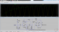
Based on a previous circuit that was generously designed by @ronv, I came up with this:

The motor data in the sim is arbitrary. That includes its series resistance and inductance. I put in those values because they were the ones whose results made sense for a 1/10 hp (74.6W) 90 VDC motor.
The motor is being fed a fully rectified (but unregulated) waveform from a 120VAC rms supply. PWM is applied to the motor after the rectifier, although that is not shown in this diagram
C2 is there to help smooth its output. The output's waveform is very similar to the input if that cap is omitted. Ideally, I'd like the output to be a smooth straight line.
I intend to connect its output to an ADC interfaced to an MCU
Questions:
Any other observations would be thoroughly appreciated.
Based on a previous circuit that was generously designed by @ronv, I came up with this:
The motor is being fed a fully rectified (but unregulated) waveform from a 120VAC rms supply. PWM is applied to the motor after the rectifier, although that is not shown in this diagram
C2 is there to help smooth its output. The output's waveform is very similar to the input if that cap is omitted. Ideally, I'd like the output to be a smooth straight line.
I intend to connect its output to an ADC interfaced to an MCU
Questions:
- Is this circuit properly protected against the commutation surges of a DC motor?
- Are the values of the resistors used in the opamp more or less the right ones for this purpose?
- Is C2 the best option for smoothing its output?
- Is there a way to isolate this circuit from either the intended ADC, or the MCU?
Any other observations would be thoroughly appreciated.
Attachments
-
 148.3 KB Views: 2
 -
3.6 KB Views: 2
") .
.


