8 sensors to one external interupt with count on a pic?

Thread Starter

spinnaker

Joined Oct 29, 2009
7,830
Imagine 8 Hall Effect sensors in each one of the slots below. There will be a disk spinning above the slots. The disk contains the magnet. I need to know when each one is tripped but I don't want to have to use 8 external interrupts. I was thinking maybe an 8 to 1 multiplexer but I have none on hand. Would there be another way to do this?

Also can't I use the CCP to interrupt say on the 4th interrupt? Is this the Compare mode, toggle output on match bit? And the CCPRxL and CCPRxH for the count? Never used CCP before except for PWM.


P.S. I will also have a "home sensor" to reset the "slot" counter.
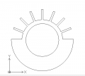


upload_2018-10-30_21-10-36.png
 

Attachments

Last edited:

nsaspook

Joined Aug 27, 2009
16,363
Why do think you need individual interrupts for each position? I could see the utility of a HOME and slot START interrupt to calculate rotational timing to first physical location on the fly if the RPM varies per revolution.
 

Thread Starter

spinnaker

Joined Oct 29, 2009
7,830
Why do think you need individual interrupts for each position? I could see the utility of a HOME and slot START interrupt to calculate rotational timing to first physical location on the fly if the RPM varies per revolution.

With 8 sensors I don't need to worry about timing. and the bonus is that it turns into a Frankenstein's Monster project. Or a cut down version of a Rube Goldberg project. ;)
 

nsaspook

Joined Aug 27, 2009
16,363
With 8 sensors I don't need to worry about timing. and the bonus is that it turns into a Frankenstein's Monster project. Or a cut down version of a Rube Goldberg project. ;)
You will still need to worry about timing even with 8 slot position sensors because you need timing information to decide digit selection over the slot unless each digit is also decoded as it passes each slot.
 

Thread Starter

spinnaker

Joined Oct 29, 2009
7,830
You will still need to worry about timing even with 8 slot position sensors because you need timing information to decide digit selection over the slot unless each digit is also decoded as it passes each slot.

Not of I have a magnet for each character.

I will likely go with the timer and one sensor / magnet. But I just want a backup plan and just want to look at other approaches.

So how would I do the 8 sensors? Would an 8 to 1 multiplexer be the only way or are there other ways to do this?
 

nsaspook

Joined Aug 27, 2009
16,363
Not of I have a magnet for each character.

I will likely go with the timer and one sensor / magnet. But I jsut want a backup plan and just want to look at other approaches.

So how would I do the 8 sensors? Would an 8 to 1 multiplexer be the only way or are there other ways to do this?
If think the problem with that is digit information is still ambiguous because all 8 interrupts would trigger each time digits align with slots if the digit magnet spacing is the same. With a 64MHz 8-bit processor you have plenty of power to just strobe a led(s) in the correct time sequence to display all digits in the proper place with one home (first digit slot position) sensor if the RPM is constant with the proper algorithm to translate physical locations to timer counts for a timer/compare interrupt at the proper slot and disk position for each digit of the clock string in sequence. Adding a second index (second digit slot position) sensor and interrupt would be useful to provide that physical location (for slot and disk number offsets from home) timer counts information.
 
Last edited:

Sensacell

Joined Jun 19, 2012
3,786
The 8 magnetic sensors will never have exactly the same pitch spacing, your characters will look wonky.
Might work with an optical sensor and a precision photo-etched flag wheel, but with magnets, the trip point will be all over the place.

The cleanest way is to use a chopper disc with 4 or eight blades, along with one Home sensor.
(or make one flag longer and use that to detect HOME)
Use the capture-compare to measure the time-per slot, divide this down into a pixel clock interrupt that applies to the next cycle. (hint: make the pixel pitch a power of 2 so the divide is a quick bit shift, not a painfully slow divide subroutine)

This way you can create a very fine pitched pixel clock that is always aligned. I have done this with only a single home sensor, works perfect if the rotor inertia is high enough so the speed is stable, adding more blades helps to reduce the jitter even more.
 

Picbuster

Joined Dec 2, 2013
1,059
Imagine 8 Hall Effect sensors in each one of the slots below. There will be a disk spinning above the slots. The disk contains the magnet. I need to know when each one is tripped but I don't want to have to use 8 external interrupts. I was thinking maybe an 8 to 1 multiplexer but I have none on hand. Would there be another way to do this?

Also can't I use the CCP to interrupt say on the 4th interrupt? Is this the Compare mode, toggle output on match bit? And the CCPRxL and CCPRxH for the count? Never used CCP before except for PWM.


P.S. I will also have a "home sensor" to reset the "slot" counter.


View attachment 162791
I did had a similar project and did an 'and' of all the sensors and put this into the interrupt.
Each line is connected to an input.
when a int arrives the int routine will detect the which sensor is generating the int.

Using a mux (8->3) will save some mpu pins.

Picbuster
 

Ian Rogers

Joined Dec 12, 2012
1,136
Personally... I would hook them all up to an IOC port and trip the interrupt on change rather than individually!

One read per change...
 

BobaMosfet

Joined Jul 1, 2009
2,211
This can be done so much simpler.... The only thing you need is the hall sensor, one interrupt, and everything else is logic.

So... how fast is the disc spinning. That's the only question that should exist in your mind right now, because everything else you do, depends on that.
 

nsaspook

Joined Aug 27, 2009
16,363
This can be done so much simpler.... The only thing you need is the hall sensor, one interrupt, and everything else is logic.

So... how fast is the disc spinning. That's the only question that should exist in your mind right now, because everything else you do, depends on that.
Exactly. The only extension from this demo is the added dimension of varying positions where the strobe happens to select digits on the disk during rotation but that's a time calculation for offset too.
2018-01-03_12-06-35.jpg

For this demo I did use degrees (radian) on a Linux host to calculate timing to dynamically update line motion using a serial link to a command parser on the PIC but the PIC controlling the device only used the time calculations from that to modify the original timing sequence.

Linux control code.
https://github.com/nsaspook/pov_control/blob/master/main.c
 
Top