74HC4060

Thread Starter

MATT838383

Joined Jul 31, 2019
144
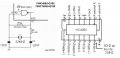
Hello everybody i have a problem to generate a 2mhz signal with a quartz of 32mhz on pin7 of the HC4060 the output is about 50HZ instead of 2mhz!
here is my schematic:
thank you!
 

Attachments

Audioguru again

Joined Oct 21, 2019
6,826
You probably built the circuit on a solderless breadboard and the messy wires all over the place are picking up the 50Hz electricity radiated in the walls of your home.
Another problem is that your circuit shows no power supply voltage.
Another problem is that your capacitor values are too low.
 

Attachments

dl324

Joined Mar 30, 2015
18,326
the max frequency is 35mhz
Only at 25C:
1582830410862.png

You also need to deal with parasitics in the breadboard. It would take some careful consideration to get something to operate at 32MHz. Have you looked at the waveforms with a scope and made sure you don't have any antennas picking up line frequency?
 

sagor

Joined Mar 10, 2019
1,049
As well, what power supply is being used? Does it have any 50Hz ripple in it? If so, that may be echoed in the chip somewhere, causing irregular results.
If using some switching regulator, that can cause problems too, use a linear regulated power supply if possible, or try different ones to see if the problem follows a certain supply.
That 35Mhz is a rating that probably only works on a properly designed PCB, and will not be necessarily that stable on a breadboard. You are pushing the limits of the chip....
EDIT: Most 74HC4060 series are rated to a maximum Vcc of 7V, not 12V. Putting +12V on it may blow the chip....
 
Last edited:

MisterBill2

Joined Jan 23, 2018
27,513
Is it possible that the crystal is a 32KHz device? Those are frequently used with a 4060 IC to generate low frequency pulse trains. So my first suggestion is to use that frequency counter to verify the oscillator frequency at pin #10. But use a low capacitance probe to do it.
I have had a lot of problems with that IC trying to get the crystal oscillator to have a decent waveform, and so it may be that you have the wrong amount of feedback.
AND the TS states that it is running on a battery, so not much ripple there. BUT it may possibly be a poor ground connection to the frequency counter. that can be verified by checking the frequency at other pins.
 

MisterBill2

Joined Jan 23, 2018
27,513
If the TS is in a part of the world where the mains frequency is 50 HZ a grounding problem would be the first thing that I would suspect. If not, then possibly a problem with the frequency counter threshold adjustment. And last, probing the wrong pin on the IC. . I do suggest probing other output pins to see what frequencies are found there. That can provide some useful insight.
 

Audioguru again

Joined Oct 21, 2019
6,826
Yes, you destroyed the 74HC4060 IC because its absolute maximum Vcc is 7V.
A solderless breadboard cannot be used with radio frequencies and low value capacitors.
Your capacitor values were too small anyway.
 

Thread Starter

MATT838383

Joined Jul 31, 2019
144
kubeek
Hi Kubeek its a velleman dvm4100
Audioguru again
Hi yes on vcc i have put a 6vdc! the same problem!maybe with the good capacitors it could work! it show on datasheet a 100pf and a ajustable 37pf!
atferrari
Hi i have put a 16mhz and 8mhz and the 4060 is unstable ive changed even with another HC4060!
MisterBill2
Hi mbill2 i have try differnet pinouts and the result is uncorrect example:8MHZ on pin 1=8000000/4096=1953(on pdf)
ON the circuit=31khz and unstable!
ericgibbs
Hi Eric: yes test with a counter!
thanks
 

MisterBill2

Joined Jan 23, 2018
27,513
OK, then the problem is an unstable oscillator portion of the circuit, which is the same type of problem that I have had. One difference is that I was using the CD4060, which is not the high speed version. The RCA manual lists the maximum supply as 20 VDC, while the Motorola 74HC4060 is listed with the max supply as 6 volts.
So I think that your feedback resistor is far to low a value, and probably the capacitors are also too small. And my comment in post #13 still holds.
And you are not the only one to have problems with the oscillator circuit of the 4060. Look in the Motorola "High Speed CMOS Logic Data" book, the design process given is not trivial. The print is too small for me to scan and post, though, or I would do that. The 17pF seems to be the device capacitance, not what to use externally.
Possibly somebody else has been more successful with this device, and could share their insights.
 
Top