 Facebook
 Google
 GitHub
 Linkedin
I recently did a Lab using a 741 Op Amp. I was asked to write my observations of what's happening with the output signal relating to the input.
In my pictures I have different scenarios during the experiment. I'm unsure if in my observations i'm explaining what's happening correctly or covering everything that's taking place. Please read the scenarios taking place in the pictures and critique my observations.
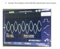
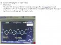
One scenario the Rf is replaced by a 10K Potentiometer and the resistance is varied. Please assist in explaining to me what's taking place as i'm also unsure.
Thanks for the help all
In my pictures I have different scenarios during the experiment. I'm unsure if in my observations i'm explaining what's happening correctly or covering everything that's taking place. Please read the scenarios taking place in the pictures and critique my observations.
One scenario the Rf is replaced by a 10K Potentiometer and the resistance is varied. Please assist in explaining to me what's taking place as i'm also unsure.
Thanks for the help all
Attachments
-
 16.2 KB Views: 20
 -
 63.2 KB Views: 20
 -
 67.7 KB Views: 19
 -
 60.8 KB Views: 19


