
5v Power Supply outputing 5.43v

ScottWang

Joined Aug 23, 2012
7,505
You said these in the 8# -- some other 5v power chargers outputting 5.0v
Did you measure them when you used load, how many voltage do they left?
 

Thread Starter

CrAcKeZ

Joined Feb 4, 2015
15
You said these in the 8# -- some other 5v power chargers outputting 5.0v
Did you measure them when you used load, how many voltage do they left?
I have a 5v 2A power supply, 5.0v on multimeter(no load) with a 1 watt load it's still 5.0v I didn't test it at 1A or more I'll try later on and see how it goes

Going to measure my original OnePlus One(charger 5v 2.1A) and an apple charger (5.2v 2.4A) - No load on both (I've charged many phones with the apple charger no issue what so ever)

EDIT:

4.98v OnePlus One original charger(no load)
5.20v the apple charger as stated(no load)

Still far from 5.44v

(Just find out a diode laying around, LH FR155 - will this do the trick? I also find this about it, it might help you understand better than I do http://www.alldatasheet.com/datasheet-pdf/pdf/59062/DIODES/FR155.html )
 
Last edited:

ScottWang

Joined Aug 23, 2012
7,505
I have a 5v 2A power supply, 5.0v on multimeter(no load) with a 1 watt load it's still 5.0v I didn't test it at 1A or more I'll try later on and see how it goes

Going to measure my original OnePlus One(charger 5v 2.1A) and an apple charger (5.2v 2.4A) - No load on both (I've charged many phones with the apple charger no issue what so ever)

EDIT:

4.98v OnePlus One original charger(no load)
5.20v the apple charger as stated(no load)

Still far from 5.44v

(Just find out a diode laying around, LH FR155 - will this do the trick? I also find this about it, it might help you understand better than I do http://www.alldatasheet.com/datasheet-pdf/pdf/59062/DIODES/FR155.html )
When 5.4V that it works maybe drop down to 5.2V, it is under 5% tolerance, if you tested as that, then it's ok.

For a modern CMOS world not the TTL 4.75~5.25V age, so if the voltage far from 5V is not a big deal, and it has only a little higher 0.2V, if the current is higher as 4A then the voltage will drop down some more.
 
Last edited:

DC_Kid

Joined Feb 25, 2008
1,242
maybe try another brand of 5vdc wall wart? the one you have may be zener clamped to 5v but not exactly spot on. most modern day std soic/smd sized regulators should be able to clamp the output extremely close to 5vdc.
any way you can scope the output of that wall wart with say a 200mA load on it, wondering if your meter is seeing ripple and displaying voltage off from 5vdc.
 

Thread Starter

CrAcKeZ

Joined Feb 4, 2015
15
maybe try another brand of 5vdc wall wart? the one you have may be zener clamped to 5v but not exactly spot on. most modern day std soic/smd sized regulators should be able to clamp the output extremely close to 5vdc.
any way you can scope the output of that wall wart with say a 200mA load on it, wondering if your meter is seeing ripple and displaying voltage off from 5vdc.
If it was to buy another power supply we wouldn't have this thread :p trying to fix this and why not expand my knowledge from some people that know more than me on the subject
I'll try to solder the "LH FR155" I've found and see how it goes :}
 

DC_Kid

Joined Feb 25, 2008
1,242
If it was to buy another power supply we wouldn't have this thread :p trying to fix this and why not expand my knowledge from some people that know more than me on the subject

I'll try to solder the "LH FR155" I've found and see how it goes :}
well, your diode will drop the voltge ~0.64v (typical diode), however, i recommend to also add a cap aft of the diode. why you ask, because if the supply is bad ripple under any loads then the diode is gonna make the dc power look very choppy as the ripple reaches diode threshold the diode will shut off, etc. a cap aft of diode will help supply some voltage when diode is off (if it goes off). you might think about clamping the voltage using a zener diode. i would like to see your supply on a scope w/ and w/o some loads on it.
 
Last edited:

Thread Starter

CrAcKeZ

Joined Feb 4, 2015
15
well, your diode will drop the voltge ~0.64v (typical diode), however, i recommend to also add a cap aft of the diode. why you ask, because if the supply is bad ripple under any loads then the diode is gonna make the dc power look very choppy as the ripple reaches diode threshold the diode will shut off, etc. a cap aft of diode will help supply some voltage when diode is off (if it goes off). you might think about clamping the voltage using a zener diode. i would like to see your supply on a scope w/ and w/o some loads on it.
I know what a cap does(essentially it's a buffer), I have a super capacitor module in my e-bike as a buffer(don't ask me how much I've paid about it:p all I can say is that's 59.4v 22.72F(22x 500F 2.7v))

Any recommendations on the capacitance? ..I have some 6.3v capacitors laying around

P.S. 0.64v would be much resulting 4.8v although I'll try this FR155 diode I have to check it out
 

DC_Kid

Joined Feb 25, 2008
1,242
hard to say if a 6.3v cap will be ok, we have no idea what that dc output looks like on the scope. i would go for something like 12-15v rated cap @ approx 60-100uF.
 

Thread Starter

CrAcKeZ

Joined Feb 4, 2015
15
hard to say if a 6.3v cap will be ok, we have no idea what that dc output looks like on the scope. i would go for something like 12-15v rated cap @ approx 60-100uF.

The power supply has 5.44v with no load and if I put the diode it will drop further why need 12-15v? I mean I have some 400v capacitors lets put these :p

P.S. yesterday I didn't manage to try the diode, hope today I can get my hands on it, if it drops 0.64v(or a result of 4.8v) it's no use, I'll need 5 or 5 and a bit to be safe
 

alfacliff

Joined Dec 13, 2013
2,458
I have worked on a few of these type wall warts, on some there is a zener diode near the output filter caps that provides feedback throuth the opto isolator (black 4 legged dohichey) to the switcher. maybe the zenner is bad or the filter caps are fading.
 

DC_Kid

Joined Feb 25, 2008
1,242
The power supply has 5.44v with no load and if I put the diode it will drop further why need 12-15v? I mean I have some 400v capacitors lets put these :p

P.S. yesterday I didn't manage to try the diode, hope today I can get my hands on it, if it drops 0.64v(or a result of 4.8v) it's no use, I'll need 5 or 5 and a bit to be safe
5.44v ? from what device did you get that # ?
ever put bad ripple dc output into a DVM before ??
you really need to scope the output to be able to determine what exactly it is you have, etc.
 

Thread Starter

CrAcKeZ

Joined Feb 4, 2015
15
5.44v ? from what device did you get that # ?
ever put bad ripple dc output into a DVM before ??
you really need to scope the output to be able to determine what exactly it is you have, etc.
Quoted from 1st post

"I've ordered a power supply of 5v 4A to use it as a microusb charger(for any type of phone or tablet)"

Also:

"I manage to find a 6Ω resistor ..pretty good load, so I've connect it and measure it final volts 5.26v and current with this 6Ω(50W it's big :p) resistor? 0.821A or a total of ~4.32watt"

Wait you're replying without know the subject? :eek:

P.S. Didn't find time today to try the diode solderring, but tommorow I have little spare time and I'll post results on Morning(Greece time GMT+2:00)
 

DC_Kid

Joined Feb 25, 2008
1,242
the #'s dont make sense to me. 5.26v and 6ohm load, that should measure something closer to 0.876A. go buy a better wall wart. you can crack this one open to see whats there (whats not there), etc.
 

Thread Starter

CrAcKeZ

Joined Feb 4, 2015
15
the #'s dont make sense to me. 5.26v and 6ohm load, that should measure something closer to 0.876A. go buy a better wall wart. you can crack this one open to see whats there (whats not there), etc.
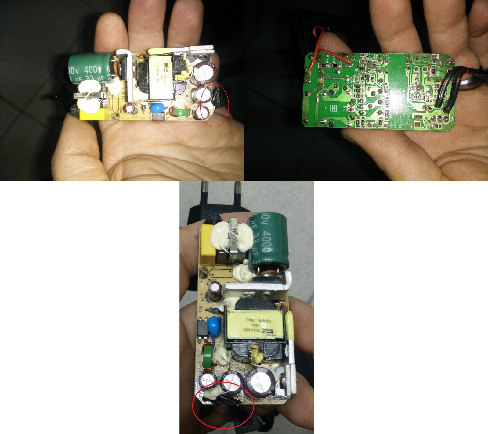
Check 1st post I've got some pictures there(quality wise ...sucks)

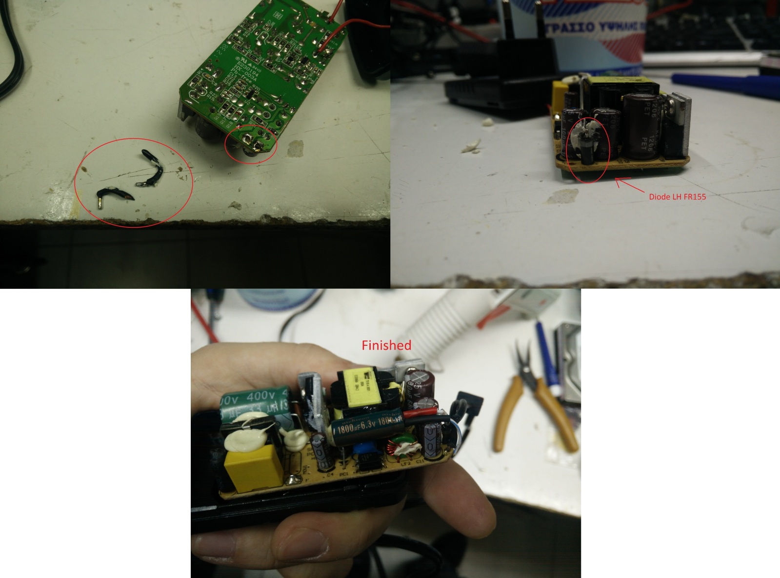
With the LH FR155 diode the voltage is 5.10v we're good(I've changed the cables to the proper location-where the board was suppose to output the voltage, not where the Chinese guy put the connections - check 1st picture)

EDIT: so final results

How it was(Before):


Where u see circles is where the board has the output(Chinese had it on a capacitor rather the the board output circuit - don't know why)

And how it's after my mods:


About the capacitor I had some laying around, it's big alright but it fits so I really don't care :p - I'll test it in an old phone today and see how it goes(if it's capable of charging it, it won't burn anything for sure)
 
Last edited:

DC_Kid

Joined Feb 25, 2008
1,242
what are the IC's on each of those AL heat sinks ?? is that small 4 prong dip a fuse of some sort. whats that 400v cap for? just because you measure 5.1v doesnt mean so much, need to see what it looks like on scope, etc. my cheapy Harbor Freight palm sized 12vdc/120vac inverter measures ~120vac on my Fluke DVM, but on scope the 120vac is horrible shape and causes my laptop power supply to run hot. i think you understand my points, so be careful to what you are powering with this supply, etc.

and to note, it went from 5.44v to 5.1v with diode ??
 

Thread Starter

CrAcKeZ

Joined Feb 4, 2015
15
what are the IC's on each of those AL heat sinks ?? is that small 4 prong dip a fuse of some sort. whats that 400v cap for? just because you measure 5.1v doesnt mean so much, need to see what it looks like on scope, etc. my cheapy Harbor Freight palm sized 12vdc/120vac inverter measures ~120vac on my Fluke DVM, but on scope the 120vac is horrible shape and causes my laptop power supply to run hot. i think you understand my points, so be careful to what you are powering with this supply, etc.

and to note, it went from 5.44v to 5.1v with diode ??
Ye I get your points, that's why I'm not gonna test it on my primary phone(but my second in command :p)

Yes 5.44v -> Diode -> 5.10v
 
Top





