Facebook
 Google
 GitHub
 Linkedin
Hi,
I want to create a home-made power supply for a Raspberry pi + USB hub, I am looking for something along the lines of a 1.5-2A 5V regulated power supply, and would like to also have it attached to a backup battery in the event of a power failure
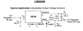
I was going to start off with this circuit, but wanted to modify it to suit my needs and thought I would ask for some help before I started ordering parts since I don't have much experience with circuits, I have a programming background

my first "obstacle" is that I have a 24V power source that I would like to use, as opposed to a 12V one as shown in the diagram. The LM2596 I am planning to use should support up to 37V, but I wanted to know if there are any other changes I should make to the circuit knowing that.
second, what would be the best way to attach a battery? I already have 2x 3.7v 2500maH li batteries from a dead spare phone charger (the circuit died and I disassembled it), or I could also play with some standard 1.2v aa or aaa batteries that I have lying around the house (I would prefer not to buy stuff unless I need to, and batteries seem expensive) - would it be OK to just combine a 3.7 v and a 1.2v battery in series and hook them up directly to the 5v power, or would this kill the batteries? (They are only for backup, and won't be used on a regular basis), or would it be best to put them before the power regulator? I am not looking for a long runtime, something along the lines of 5-10 minutes should be fine (but I think I will end up with longer due to the size of the batteries relative to my power requirements)
third, if possible I would like to hook up the backup battery circuitry to the GPIO pins of the raspberry pi, which are capable of 3.3 (not 5V!) so that the device knows if it's on battery power and how much is left (if possible, but maybe I am getting ambitious - I just want the device to shut itself down)
P.S. I would prefer to stick with the LM2596 if possible as I have already ordered that
I want to create a home-made power supply for a Raspberry pi + USB hub, I am looking for something along the lines of a 1.5-2A 5V regulated power supply, and would like to also have it attached to a backup battery in the event of a power failure
I was going to start off with this circuit, but wanted to modify it to suit my needs and thought I would ask for some help before I started ordering parts since I don't have much experience with circuits, I have a programming background
my first "obstacle" is that I have a 24V power source that I would like to use, as opposed to a 12V one as shown in the diagram. The LM2596 I am planning to use should support up to 37V, but I wanted to know if there are any other changes I should make to the circuit knowing that.
second, what would be the best way to attach a battery? I already have 2x 3.7v 2500maH li batteries from a dead spare phone charger (the circuit died and I disassembled it), or I could also play with some standard 1.2v aa or aaa batteries that I have lying around the house (I would prefer not to buy stuff unless I need to, and batteries seem expensive) - would it be OK to just combine a 3.7 v and a 1.2v battery in series and hook them up directly to the 5v power, or would this kill the batteries? (They are only for backup, and won't be used on a regular basis), or would it be best to put them before the power regulator? I am not looking for a long runtime, something along the lines of 5-10 minutes should be fine (but I think I will end up with longer due to the size of the batteries relative to my power requirements)
third, if possible I would like to hook up the backup battery circuitry to the GPIO pins of the raspberry pi, which are capable of 3.3 (not 5V!) so that the device knows if it's on battery power and how much is left (if possible, but maybe I am getting ambitious - I just want the device to shut itself down)
P.S. I would prefer to stick with the LM2596 if possible as I have already ordered that
Attachments
-
 45.6 KB Views: 235