>5Mhz oscillator with discrete logic chips

Thread Starter

bob800

Joined Dec 10, 2011
50
Hello,

I need a 12.6 MHz square wave signal for a video generator circuit. Now I know that a crystal oscillator would be recommended for this, but I'd like to test my existing circuitry before I purchase the final parts (I do not have any crystal oscillators).

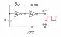
I tried using a 4049 inverter (see attachment for configuration), and after removing the capacitor and lowering the value of R to the point just before oscillation stopped, I measured a frequency of 5 MHz with my oscilloscope. Is there any other type of circuit configuration that could give me a higher frequency? Or am I limited by switching speed of the CMOS chips themselves?


Thanks,

bob800
 

Attachments

MrChips

Joined Oct 2, 2009
30,801
You are going to encounter difficulty getting a CMOS chip to work at that frequency.

74S124 would be a better choice. These will work to 85MHz.
 

bertus

Joined Apr 5, 2008
22,276
Hello,

Did you read in the data sheet, that the speed of the inverters are dependend on the power supply?
When the power supply is 12 Volts, the speed will be much higher as when 5 Volts is used.
Also the stability of a RC oscillator will be far from ideal.

You could even make an oscillator with a ring of three gates.
The frequency will be dependend on the supplied voltage.

Bertus
 
Last edited:

Thread Starter

bob800

Joined Dec 10, 2011
50
Hello,

Did you read in the datasheet, that the speed of the inverters are dependend on the powersupply?
When the powersupply is 12 Volts, the speed will be much higher as when 5 Volts is used.
Aslo the stability of a RC oscillator will be far from ideal.

Bertus
Thanks for the reply. Yes, the 5 MHz was obtained after cranking up the voltage to the maximum 15 volts.

You are going to encounter difficulty getting a CMOS chip to work at that frequency.

74S124 would be a better choice. These will work to 85MHz.
I don't have any 74S series ICs... but I do have a 7400 and a 7404... would these produce higher frequencies than the 4049?
 

BillO

Joined Nov 24, 2008
999
You could try the attached circuit using various Schmidt trigger inverters. The frequency will be given by f=1/(RC) provided that RC is significantly longer than the delay of the inverters.

40 series CMOS is not known to be overly speedy.
 

Attachments

bertus

Joined Apr 5, 2008
22,276
Hello,

Did you see my last remark in my previous post?
A ring of 3 gates will make an oscillator.
If the frequency is to high, you can use 5 or 7 gates.
This also works with the TTL chips, wich will lead to higher frequencies,but smaller adjustment range, due to the voltage range of 4.75 to 5.25 Volts.

Bertus
 

Ron H

Joined Apr 14, 2005
7,063
You could try the attached circuit using various Schmidt trigger inverters. The frequency will be given by f=1/(RC) provided that RC is significantly longer than the delay of the inverters.

40 series CMOS is not known to be overly speedy.
Build this with 74HC14, 2.2k, and a trimmer cap that includes 10pF within its range. Vcc must be 5V, and build the breadboard on copperclad with a ground plane. The "dead bug" technique will minimize stray capacitance (see example below). You should be able to get at least 12.6MHz.
DON'T use a solderless breadboard. Their stray capacitance is too high.
 
Last edited:

Thread Starter

bob800

Joined Dec 10, 2011
50
Build this with 74HC14, 2.2k, and a trimmer cap that includes 10pF within its range. Vcc must be 5V, and build the breadboard on copperclad with a ground plane. The "dead bug" technique will minimize stray capacitance (see example below). You should be able to get at least 12.6MHz.
DON'T use a solderless breadboard. Their stray capacitance is too high.
Thanks for the suggestion! Is the Schmitt trigger necessary, or could I substitute the 74HC14 with a 7404? (Keep in mind that this oscillator is only for testing purposes, and I'll replace it with a crystal once I get one).
 

takao21203

Joined Apr 28, 2012
3,702
This is quite interesting.
However it also works well with small prototyping PCBs turned upside down (copper at the top). Parasitic capacitance is not normally an issue.

Proto PCB should have single hole pads, not strips.

I'd say this is good for 50 MHz and more, even 100MHz.

Only for VHF (television etc.) you need to route some signals in free air.

Breadboards aren't really good. However, I used them for circuits producing some MHz. I made a jouletheif circuit, only with 2 coils. And reduced down to 2.2uH.

It was very sensible. The transmitter coil inserted with one pin only! If you'd tap it with a big screwdriver, the LED brightness would go down a lot. If you'd tap before the transmitter coil, nothing would happen.

Adjacent rows of course have a rather high capacitance!!
 

Ron H

Joined Apr 14, 2005
7,063
Thanks for the suggestion! Is the Schmitt trigger necessary, or could I substitute the 74HC14 with a 7404? (Keep in mind that this oscillator is only for testing purposes, and I'll replace it with a crystal once I get one).
I think a Schmitt trigger is the only reliable RC oscillator you can build with one gate (inverter, in this case) and a single RC network. RC oscillators with multiple inverters are slower because of the propagation delays of the inverters. As Bertus pointed out, you could build a ring oscillator with 3 gates in a feedback loop, but tuning the frequency with the supply voltage makes interfacing with other logic somewhat problematic.
Attached is an oscillator works in simulation. I didn't breadboard it.
 

Attachments

Top