Facebook
 Google
 GitHub
 Linkedin
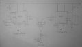
I am building a pitch-only theremin and I designed this, as it was the simplest circuit I could understand lol. I was hoping to get feedback as to if this looks like it will work. The circuit consists of two 555 timer circuits wired in the astable mode. the idea is that the right ("Fixed") one oscillates at about 447kHz and the left one oscillates at between 444kHz and 447kHz, depending on the position of the hand (far away, the two oscillators have equal frequencies so no sound is produced; the 5k pot is to tweak the freqeuncies so that the base frequencies match). I assumed the maximum capacitance of the antenna and hand is around 1 pF. I'm not sure if the 555 can run that fast, or if it was okay to use such a small cap in the frequency determining part of each 555 circuit, but from what I've researched the values do not seem too unreasonable. the 100 uF caps before the XNOR gate are to get rid of DC. the XNOR is supposed to sum the two square waves, with a high output only when both signals are the same voltage (both low or both high). then the final low pass filter to get rid of the 400kHz+ overtone and leave just the beat frequency of the two signals.
So my questions are:
-does this seem like it would work when soldered on a pcb (not breadboard)?
-should I run the output into computer speakers (that have a built in amplifier) or will this power its own speaker?
I apologize if this post is overlong or unintelligible, but I'd appreciate any help I can get!
So my questions are:
-does this seem like it would work when soldered on a pcb (not breadboard)?
-should I run the output into computer speakers (that have a built in amplifier) or will this power its own speaker?
I apologize if this post is overlong or unintelligible, but I'd appreciate any help I can get!
Attachments
-
 211.5 KB Views: 83