 Facebook
 Google
 GitHub
 Linkedin
Alll the 555 watchdog timers I have found are trying to reset the processor after a large number of seconds. My problem is different.
I am multiplexing LEDs, pushing them to their limit of about 100mA, with a 100us pulse. Now, the question arises as to what happens under conditions that would interfere with the pulse. So what I am doing is creating a "watchdog" that turns on for about 100ns and then turns off
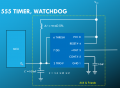
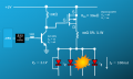
I am attaching the schematics. The first is the schematic for the "555 & friends". Note that I am not discharging the capacitor with the DISCH pin of the 555. If there is no trigger, the capacitor charges to 2/3Vcc and drops the output low. It stays at low until the processor pulls its heartbeat pin low. This discharges the capacitor, and, falling below 1/3Vcc, starts the next cycle Thus, the pulse is hardware-generated, not software-generated. If the processor fails to trigger a pulse, there is no pulse to the LEDs, so there is no burnout. The PowerPoint slides are animated, and the "explosion" illustrates the failure mode if there is not a controlled trigger. The 100us pulse controls all the LEDs; an NMOS transistor selects which column is activated. While it is true that, in this illustration, the 555 has more than enough power to provide a source for a single LED, the final design will have a dozen or so in each column, hence the use of higher-power MOSFETs (1200mA).
This protects the LED array from either software failure or debugging by single-stepping. The driving pulse is limited entirely by the 555 timer.
My change in removing the DISCH pin from the circuit seems a bit odd, but I thought carefully about this; I don't want the capacitor to discharge unless there is a distinct negative transition on the TRIG line, and whether that signal is held low or high for too long should not matter. I have been debating putting a capacitor in series with the I/O pin to convert the output signal to a pulse, but I am not sure about how I should do this or how to select the size.
I am multiplexing LEDs, pushing them to their limit of about 100mA, with a 100us pulse. Now, the question arises as to what happens under conditions that would interfere with the pulse. So what I am doing is creating a "watchdog" that turns on for about 100ns and then turns off
I am attaching the schematics. The first is the schematic for the "555 & friends". Note that I am not discharging the capacitor with the DISCH pin of the 555. If there is no trigger, the capacitor charges to 2/3Vcc and drops the output low. It stays at low until the processor pulls its heartbeat pin low. This discharges the capacitor, and, falling below 1/3Vcc, starts the next cycle Thus, the pulse is hardware-generated, not software-generated. If the processor fails to trigger a pulse, there is no pulse to the LEDs, so there is no burnout. The PowerPoint slides are animated, and the "explosion" illustrates the failure mode if there is not a controlled trigger. The 100us pulse controls all the LEDs; an NMOS transistor selects which column is activated. While it is true that, in this illustration, the 555 has more than enough power to provide a source for a single LED, the final design will have a dozen or so in each column, hence the use of higher-power MOSFETs (1200mA).
This protects the LED array from either software failure or debugging by single-stepping. The driving pulse is limited entirely by the 555 timer.
My change in removing the DISCH pin from the circuit seems a bit odd, but I thought carefully about this; I don't want the capacitor to discharge unless there is a distinct negative transition on the TRIG line, and whether that signal is held low or high for too long should not matter. I have been debating putting a capacitor in series with the I/O pin to convert the output signal to a pulse, but I am not sure about how I should do this or how to select the size.
Attachments
-
 145.2 KB Views: 35
 -
 120.2 KB Views: 35


