Facebook
 Google
 GitHub
 Linkedin
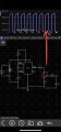
What do you intend to drive with this signal? Did you want triangle wave, or is exponential okay?Currently trying to figure out a way to recreate my original wave form without a transistor and from a regulated lower voltage.
555 timer oscillating circuit with PNP transistor trouble
- Thread starter Badbusiness
- Start date