why? ive tried with your drawing post 40 and its the same result maybe my 555 is wrong! i was trying to have an external clock! and see if it vary! sorry for disturbs
Where did you get a clock frequency of 195Hz?
My simulation shows a clock frequency of ≈1.38KHz.
And why does your circuit have a 1k resistor and 10nF cap at the 741 output when mine doesn't?
As I previously mentioned, a capacitor at the 741 output can cause oscillations.
If you can't carefully follow what I say or what is on a schematic, then I'm spinning my wheels here.
ok (i asume a was off topic) (i am trying with a monostable pwm method!) i have tried alone and need some explanations
the clock frequency is from a 74HC4060 with 16mhz xtal and a 4017 output of 195,3hz!
now if its possible i would like to put this frequency like reference frequency on a 555 monostable pwm(if somthing wrong just tell me) the shematic post44 is an advice from one who told me to put a 10nf between pin 5 of the 555 and ground! i have done it and there was no results! what is your opinion?
regards
What is external clock frequency range ? What resolution do you need duty cycle ? 16 bits enough ?
That would mean duty cycle resolution 1 part in ~ 65,000. Note system noise would probably cut
that down to something like 1 part in 10,000, or .01%
Note right hand window, resources used versus left. Most are left for doing additional tasks.
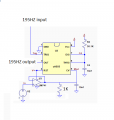
After some thought I realized the LM339 circuit could be synchronized to an external pulse.
Below is the simulation of the modified circuit with a sync input.
The free running frequency of U1 should be about 5-10% lower than the sync frequency for reliable synchronization.
To allow for component tolerances you likely would have to make R1 a pot to get the desired free run frequency.
@MATT838383 You may want to look into small Picmicro's, you most likeley could have achieved the result with a single 8 pin micro in less time than the posts have taken!
Max.
 Facebook
 Google
 GitHub
 Linkedin


")


