555 monostable trigger switch pulse generation

Thread Starter

AmIstupid

Joined Jun 9, 2024
10
I often use a 555 monostable with a switch as a trigger input, and so use a capacitor with 2 resistors to create a short pulse from a long switch to ground. See schematic. My question is, what does the diode do? I always include it, and I notice the trigger is unreliable if I don't. It's connected like a flyback diode, but there is no inductive element. I would think the cap totally discharges once the switch is opened, but apparently something is keeping the trigger pin at a potential even higher than VCC, correct? Can somebody please splain me? Thanks in advance.
555 trig conditioning.png
 

Hymie

Joined Mar 30, 2018
1,297
The purpose of the diode is to prevent the voltage on pin 2 exceeding the supply rail voltage as a result of the input to capacitor C1 going positive (when the switch is released), which might destroy the 555 timer or upset its performance.
 

dl324

Joined Mar 30, 2015
17,220
My question is, what does the diode do? I always include it, and I notice the trigger is unreliable if I don't.
The diode isn't preventing any unreliable triggering. All manufacturers likely recommend bypassing the control input if it isn't being used. Adequate supply decoupling is always assumed.

This topic has come up recently (last few months).

It would be helpful if you specified the supply voltage. But, if you're observing recommended operating conditions, the diode is overkill.

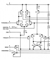
Here's the relevant portion of the circuit from a Nat Semi datasheet:
1719150641049.png
When S1 is closed, the capacitor starts charging towards the supply voltage. When the switch is opened, the cap terminal connected to the trigger input could rise to twice the supply voltage if S1 is closed for 5 RC time constants. You have 3 base-emitter junctions, a collector-base junction, and a 1k resistor with up to 16V across them.
1719151404405.png

Assuming manufacturers are using "generic" transistors (e.g. not RF or super beta), the base-emitter junctions will breakdown at around 5-6V of reverse bias. At 16V, it's unlikely that any of the b-e junctions would be broken down hard enough to cause beta degradation when using a reasonable capacitor value for coupling. Signetics suggested a 1nF cap in the application note in their 1979 Analog Applications Handbook, but 100nF is probably not too excessive. This is likely why Signetics, who contracted the original design, never mentions a clamping diode in their extensive 555 timer application note in the aforementioned handbook.
1719151792330.png
 
Last edited:

ericgibbs

Joined Jan 29, 2010
19,168
hi Ami,
This simulation shows the action of the diode in preventing a high voltage overshoot on the Trig pin, due to capacitor charge/discharge
I would always fit a diode on this type of triggering.
E
EG57_ 1829.png
 

AnalogKid

Joined Aug 1, 2013
11,223
It's connected like a flyback diode, but there is no inductive element. I would think the cap totally discharges once the switch is opened, but apparently something is keeping the trigger pin at a potential even higher than VCC, correct?
While an inductive element often is associated with a voltage spike called an "inductive kick", a capacitive element is associated with a different type of voltage spike called acharge pump.

The voltage across a capacitor cannot change instantaneously. When the switch is closed and held, C1 charges up to Vcc through R2. When the switch is opened, R1 pulls the left side of C1 up to Vcc. Without D1, this yanks the right side of C1 up to approx. 2 x Vcc. C1 immediately begins discharging through R1 + R2, but the damage takes nanoseconds. This high voltage is applied across the PNP darlington transistor configuration that is the Trigger input's internal circuit. At 5 V this is not a problem, but at 15 V it could be enough to force the transistors into reverse-breakdown.

D1 clips this voltage spike to (Vcc+0.6 V), a safe value under all operating conditions. An extra benefit of D1 is that it effectively "shorts out" R2, reducing the C1 discharge time.

ak
 
Last edited:

Thread Starter

AmIstupid

Joined Jun 9, 2024
10
That's very good information, AnalogKid. I'll need to study more about this aspect of capacitors. In my circuit, without the diode, after a few operations, the triggering becomes unreliable and requires switching to ground a few times before it works. With the diode, it is 100% reliable. Capacitors is complicated.
 

dl324

Joined Mar 30, 2015
17,220
without the diode, after a few operations, the triggering becomes unreliable and requires switching to ground a few times before it works.
The diode has nothing to do with triggering. All it does is clamp the voltage on the trigger input. If you're not using a voltage higher than 15V, you don't need it. 16V is on the edge, but Signetics wasn't concerned enough about it to suggest a clamp.

The timer is triggered when the trigger input voltage goes below Vcc/3 and has to go above Vcc/3 before the timer can time out. I'd monitor the trigger input voltage while triggering and/or look for some wiring problems (bad connections).
 

AnalogKid

Joined Aug 1, 2013
11,223
The diode has nothing to do with triggering. All it does is clamp the voltage on the trigger input.
It also shortened the reset period for C1.

The timer is triggered when the trigger input voltage goes below Vcc/3 and has to go above Vcc/3 before the timer can time out.
Nope. Has to go above (2 x Vcc) / 3. Once the internal flipflop is set, it can be reset only by either the Reset input or the Trigger input.

ak
 

sghioto

Joined Dec 31, 2017
5,438
Once the internal flipflop is set, it can be reset only by either the Reset input or the Trigger input.
ak [/QUOTE]
The Trigger must be above 1/3 Vcc and the Threshold above 2/3 Vcc to reset.
 
Last edited:

AnalogKid

Joined Aug 1, 2013
11,223
Yeah - after I posted that, I went back to the datasheet internal schematic and traced it out. You guys beat me by 13 minutes. A little senior moment.

ak
 
Top