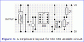
555 astable circuit for a solenoid

Thread Starter

Samuel_w

Joined May 17, 2010
9
Hi guys what i am trying to do is create for a drum kick pedal an attachment that would automatically power the kick pedal so you could train your feet to go in time with it. very useful for training purposes. The way i was thinking of doing this is using a solenoid connected to basically an arm that could clamp on the pedal and then power the solenoid to work the pedal. I am have alot of trouble designing a circuit for this though. I am an absolute beginner when it comes to this stuff i have literally no idea what to do however i have been told the 555 astable circuit is very similar and looking at them they almost do what i want to but i have no idea how to finish it off and whether i would need more powerful components than the one in the circuit on here. http://www.eleinmec.com/article.asp?3 any help please guys? thanks
 

Bychon

Joined Mar 12, 2010
469
The 555 is the right brain chip, but it can't operate a solenoid. You must attach some kind of power transistor(s) to get it to fire a solenoid. The next step is to define the solenoid in terms of voltage and current so you can figure out what goes in between the brain and the muscle.
 

Thread Starter

Samuel_w

Joined May 17, 2010
9
010 Actuator
The 010 electric actuator is a compact design for industrial applications with high demands.
The units are fitted with high quality 12v or 24v DC motors for long term reliability.


Load Capacity from
500N (50kg) at 4mm/second to
300N (30kg) at 7mm/second

Stroke up to 100mm
Supply 24v DC (standard)
Rating 40% at full load
Protection IP54


Ok well i think this is the solenoid actuator i want to use but i have no idea how to convert it into voltage and current as you said
 

Thread Starter

Samuel_w

Joined May 17, 2010
9
Technical Data​
M10 LH10 LH11 LH950​
Limit Switch​
Preset Adjustable between 30 100mm

Voltage​
12VDC / 24VDC – Customer specified

Current - Nominal​
0.4A 0.4A 1.1A 1.1A

Protection​
IP40 IP54 IP54 IP54

Ambient Temperature​
-20˚C +40˚C -20˚C +40˚C -20˚C +85˚C -20˚C +85˚C

Not sure if this would help seems to say the current for it is 0.4A and the voltage is 12-24v


Bychon

Joined Mar 12, 2010
469
I think it says the 12 volt model uses 1.1 amp and the 24 volt model uses .4 amps. Do you have a DC voltage you want to use (like a car battery) or is that part of "what to build"?
 

Thread Starter

Samuel_w

Joined May 17, 2010
9
Well i was just going to have either a plug and connect it to mains or battery operated gotta build the whole thing. battery makes it more mobile while plug is easier but i think i will go with battery operated unless batteries wouldn't last very long in them
 

Bychon

Joined Mar 12, 2010
469
How to calculate a battery. Read the amp-hour rating on the label, divide by 1.1 if it's 12 volts, and divide by .4 if it's 24 volts.
 

Thread Starter

Samuel_w

Joined May 17, 2010
9
so i need a 10.8w battery? so bascially at least 11w? if its 12 volts. if its 24 volts i need a 60w battery haha quite a big change.
 

Bychon

Joined Mar 12, 2010
469
The question is, "How long will a battery last?"
If a battery has amp-hours and you divide those by amps, you get hours.
 

Thread Starter

Samuel_w

Joined May 17, 2010
9
yeah thanks i never knew what mAh was you have explained it to me thanks so if i get ones that are say 2500mAh and are 1.5v batteries i need 8 of them to make the 12v needed and they would last... 2.25 hours?
 

Bychon

Joined Mar 12, 2010
469
NiMh batteries produce 1.2 usable volts. You would need 10 of them, and they would last about 2.27 hours, as you said., but I wonder if you are going to solder a circuit together. Is that your plan?
 

Bychon

Joined Mar 12, 2010
469
What have you come up with about using that 555 chip you posted in the first question? Can you present your drawing as an attachment here? Hint: look down the page a bit and click on, "Go Advanced".
 

Thread Starter

Samuel_w

Joined May 17, 2010
9
Yeah just what i got in there i think i know where the variable resistor should go... and i know there should be a reverse diode around the solenoid but i dont know how to put that in either
 

Attachments

Bychon

Joined Mar 12, 2010
469
When I asked what you have come up with, I didn't mean, "Can you send me a drawing copied from a website?" I meant, "What have YOU come up with?"

Do you know Ohm's Law? Do you know Watt's Law? Can you calculate a resistor value from the equasions provided on the 555 demonstration page? Do you own a soldering iron? Have you ever used it? Are you waiting for me to design this for you and hand you the finished drawing?
 

Thread Starter

Samuel_w

Joined May 17, 2010
9
Me myself i have nothing so far :/ well my teacher helped draw me a diagram of the circuit, not a soldering one like that but just the diagram so i looked around for more help on it thats the best i have found. I know ohm's law. do not believe i know watt's law... i know a watt is a joule of energy per second. i cannot calculate a resistor value. i have soldering iron and i have used it. I am not waiting for you to design it for me. Any help will be appreciated so if you was to design it for me i would be very grateful or if you could show me how to work up to it that would be awesome
 
Top