500VDC/20A static IGBT switch high side gate driver with charge pump with Vcc=+3.3V

Thread Starter

fmeili1

Joined Mar 27, 2024
7
Hello all,

this is my very first post to this forum and I hope ask my questions in the correct section.

I'm trying to implement an electronic switch with an IGBT controlled by an ESP32 logic (3.3V GPIO). The IGBT acts like a static switch which stays on for a very long time (permanent) - no PWM or something else.

The load is a solar charge controller (SCC) and the power source are PV modules. None of the PV+ and PV- lines are ground connected (floating SCC design). The IGBT should switch up to 500VDC with up to 15A. For other reasons, the IGBT should switch the PV+ line so I think I need a high side driver.

On top of that, all components should be able to run with 3.3V power supply - if possible.

I found a high side driver which seems to be able to be running with Vcc=3.3V power supply (but not 100% sure). Because of using the IGBT in a static mode (permanently switched on), I think I need an external charge pump on top of the high side gate driver itself. So far I came up with the following idea with an IR2125:
1711584173873.png
View attachment 63189

I found a charge pump example in a spec which looks like this:
View attachment 63191
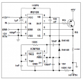
1711584190339.png
Now I'm not really sure, if I can use this example because my negative load side is NOT connected to ground (it's floating). But in the example, the negative side of the load is connected with ground and the negative side of the load is connected via a 100k resistor to the ground of the timer - I'm pretty sure this is not what I want to have, because it's a floating load.

So I left with a couple of questions:
1) How to use a charge pump (with a CMOS timer LMC555CN instead of ICM755 given in the example, to be able to run it with Vcc=3.3V) to drive a floating IGBT without ground reference of the load?
2) Will Vcc=3.3V be high enough to drive the IGBT at all. Even if the IR2125 and the LMC555CN would be able to run with Vcc=3.3V, will it be enough voltage to bring the IGBT to switch on? Or do I need at least Vcc=10V-20V to provide high enough gate voltage? I don't know how the boot capacitor and the charge pump would be able to lift the gate voltage to the required level even with a low Vcc?
3) Maybe there are better ideas how to implement such an electronic switch?

Thanks in advance for your help!

Frank
 

ronsimpson

Joined Oct 7, 2019
3,264
You normally cannot use a gate driver like the IR2125 top side that used a diode when you want to work at DC.
I have done it with an isolated power supply. There are some DC to DC 1 watt or 2 watt supplies that are good for 2000 volts of isolation. Some have 12V in and 12Vout.
Input is 12V. Output + to VB, Output - to BS. Remove diode and all of the 755 parts.
12v to 12v 1w I use these.
 

Thread Starter

fmeili1

Joined Mar 27, 2024
7
You normally cannot use a gate driver like the IR2125 top side that used a diode when you want to work at DC.
I thought with a charge pump this would be possible, but your idea with the converter, it's much simpler and I like it alot!
I have done it with an isolated power supply. There are some DC to DC 1 watt or 2 watt supplies that are good for 2000 volts of isolation. Some have 12V in and 12Vout.
Input is 12V. Output + to VB, Output - to BS. Remove diode and all of the 755 parts.
12v to 12v 1w I use these.
Maybe you could have a look at the changed schema if I understand everything correct.
1711631661079.png
1) I've removed just the diode between pin1 and pin8 and kept the C1.
2) I've attached the output of the DC-DC to pin VB (+) and VS (-)
3) Because I need 12V anyway now, I've changed the power supply of the IR2125 from +3.3V to +12V (input of the DC-DC converter) - I think it will run more stable with +12V?!

I hope I can still use the +3.3V logic to drive the IR2125 with the GPIO output of the ESP32.

Thanks a lot for your help!
 

LowQCab

Joined Nov 6, 2012
4,356
A Photovoltaic-Gate-Driver could be the only simple Component necessary.

You should never run a device right at it's Rated-Maximum-Current, ( ~50% would be much safer ),
It might be a good idea to select a higher-rated IGBT, or to parallel 2 of the current suggested part-number.
It may be more efficient to run a MOSFET instead of an IGBT, although it will be more expensive.

My suggested Dual-Photo-Voltaic-Isolated-Gate-Driver is attached. ( FDA217-ND )
It's 2 Outputs should be wired in series to create a single 18-Volt-Output,
( which may be too high for the IGBT-Gate ),
and then the IGBT's Gate should be protected with a ~14-Volt Zener-Diode,
this will insure that it will provide the maximum required
Gate-Voltage needed to achieve a fully "Turned-On" condition or "state".
No Gate-Resistor will be needed or wanted.

This Isolated-Gate-Driver may require 2 separate GPIO Outputs operating in sync to
drive the 2 Input-LEDs simultaneously because of the very-low 3.3-Volt Supply available.
The Input-LEDs should be driven at their Maximum-Rated-Current during
the "Turn-On" period to insure the fastest possible turn-on-speed.
( if the IGBT will be under a heavy-load at "turn-on" ),
( this Gate-Driver-design is comparatively "slow" and can not create very much peak-Gate-Drive-Current )
After "Turn-On" the LED-Current can be reduced significantly during static "On" conditions.
2 small Capacitors bypassing each of the LED Current-Limiting-Resistors will easily do the job.
If You need help calculating any of this just ask.
.
.
.
 

Attachments

Last edited:

ronsimpson

Joined Oct 7, 2019
3,264
The IR2125, the VS and CS should be tied together if you are not using current limit. My memory said there are two version of that part, but I could not find it just now.

I did not study the data on the little power supply. Please double check the isolation voltage. There are many parts that are almost the same.

LowQCab Makes a good point. If you are turning on/off infrequently that is a good choice. I needed fast response time and the current limit functions.

I think the IR2125 is not in production but when I checked 6 months ago there were a million on the shelf that were not sold. No one was using the part so probably they will last for a long time.
 

Thread Starter

fmeili1

Joined Mar 27, 2024
7
Thanks a lot for both of your comments. Now have to choose between two possible versions.

Version 1: High side IGBT driver with DC-DC converter as a charge pump replacement. As @ronsimpson mentioned, I've connected the CS with the VS because I don't need current sense. I removed the gate resistor and add a TVS diode between IGBT's gate and source as @LowQCab suggested.

1711678651640.png


Version 2: Opto isolated PV driver to drive the IGBT

1711679265029.png

Version 2 is a lot easier, automatically isolated, much cheaper, 3.3V logic compatible and I don't need high speed switching capabilities. The output voltage of the opto driver is high enough (12V) to drive the IGBT so I still can use it instead of a MOSFET for my application. At high current (10-20A) the forward voltage of the IGBT is even lower compared to as MOSFET (as what I have found out so far).

Each ESP32 GPIO output can drive up to 12mA permanently (no difference if used with high or low logic) , so I've done as @LowQCab suggested and put a parallel RC for the LED in series to the 330R resistor. This will result in a LED surge of 10mA at the "Turn-On" period which will be reduced to 5mA after 3.3ms.

@LowQCab: The selected IGBT has a max. of 600V and because in my solar system, no string has more than 300Voc, I will stay with this IGBT type and I know that it may be used with up to 500V per string to stay in the IGBT specs - even if it's close and not longer in the 50% safety range...
I don't know if it makes sense to add a zener diode (or TVS) in version 2, also?

So I think I will do some tests with version 2 for my application.

Thanks again for your great help!
 

kaindub

Joined Oct 28, 2019
134
Jeez
Why dont we just keep it simple. Simple is always the best solution
Since there is no PWM required, use a relay
May have to drive the output of the MCU thru a transitor and have a voltage suitable to drive te relay (12V?)
Hell a lot easier than a solid state solution.
Relays of this sort of rating (maybe a contactor) are easy to find
 

LowQCab

Joined Nov 6, 2012
4,356
When I said "~50%", I was referring to the Current-Capacity of the IGBT, not the Voltage.
If You attempt to run it at ~15-Amps, there's a chance of blowing it.
If You put 2 or 3 or even 4 IGBTs in parallel, You will be much safer and have to dissipate less HEAT.
They're cheap. and they are simple to parallel with Load-Balancing-Resistors.
I haven't done the Heat-Calculations, but it's going to be some fairly serious HEAT,
and will require a rather large Heat-Sink, preferably a Fan-Cooled-Heat-Sink.

The actual Voltage being applied will have a huge effect on the HEAT-Dissipation experienced.

Use a ~14-Volt Zener-Diode, not a TVS, in either application, to protect the Gate.
The Zener should be soldered directly to the IGBT right after
it is removed from it's protective packaging,
and before installation into the Circuit,
to prevent "accidents" with Static-Electricity.
( And You won't even know that it happened, or even when it might have happened )

Use both Channels of the Photo-Voltaic Gate-Driver, in series,
to insure that the IGBT is definitely and fully "Turned-On".
A nominal ~9 or ~10-Volts at the Gate is just not going to cut it in this application.
Don't blow-off this point .........
Study the Spec-Sheet for the reasons why.

The Schematic using the IR2125 may require a Gate-Resistor to limit Current.
Check the Spec-Sheet.

Rework your Gate-Speed-Up-Circuit to provide a ~30mA, or even up to a ~50mA start-up-boost.
This will substantially speed-up the turn-on-time and reduce HEAT generation on start-up.
It might not be a bad idea to add a single small Transistor to drive the 2 LEDs,
and then reverse the Output-Polarity of the GPIO-Pin.
If You don't want to reverse the GPIO-Output-Polarity,
use 2 small Transistors to correct the Polarity, and drive the 2 LEDs.
Continuous "On" LED-Current should preferably be ~10mA for both LEDs.
.
.
.
 

Ian0

Joined Aug 7, 2020
10,293
To ask the obvious question - does the solar charge controller not have a "disable" input that you could use to switch the PV off?
What are the unspecified reasons it cannot be switched on the negative?
If you add a charge pump or anything that is referenced to ground, then it will ground-reference the solar, so the only solution is @LowQCab 's photovoltaic driver.
 

Thread Starter

fmeili1

Joined Mar 27, 2024
7
Jeez
Why dont we just keep it simple. Simple is always the best solution
Since there is no PWM required, use a relay
May have to drive the output of the MCU thru a transitor and have a voltage suitable to drive te relay (12V?)
Hell a lot easier than a solid state solution.
Relays of this sort of rating (maybe a contactor) are easy to find
For the given range of 300-500VDC at about 10-20A there is an arc problem for all type of mechanical switches (breakers, manual switches, relays, etc.). To implement a reliable switching, these devices often implement complex arc-quenching mechanisms (arc extinguishing chambers, magnetic arc blowing, nitrogen filled, etc.). Relays of this type can be expensive compared to IGBT's.
 

Thread Starter

fmeili1

Joined Mar 27, 2024
7
When I said "~50%", I was referring to the Current-Capacity of the IGBT, not the Voltage.
If You attempt to run it at ~15-Amps, there's a chance of blowing it.
If You put 2 or 3 or even 4 IGBTs in parallel, You will be much safer and have to dissipate less HEAT.
They're cheap. and they are simple to parallel with Load-Balancing-Resistors.
I haven't done the Heat-Calculations, but it's going to be some fairly serious HEAT,
and will require a rather large Heat-Sink, preferably a Fan-Cooled-Heat-Sink.

The actual Voltage being applied will have a huge effect on the HEAT-Dissipation experienced.
OK, I think I will reduce the max. voltage and amp range to fit more my current PV situation (first idea was to make the specs a bit higher to be able to use the same circuit in installations with larger PV array sizes). So my current PV strings have a maximum of 305V and 10.9A (theoretical PV maximum).

I've done some some example calculations with two versions of IGBT:

1. low drop IGBT (STGB10NB60S) ~ $2:
It's max. ratings are Ic=29A at 25°C and Ic=16A at 100°C and a maximum Vces=600V and the max. Vge=±20V.
The typical Vce loss is 1.35V (max. 1,75V) at Ic=10A and Vge=15V.
So in my case I'll have a typical loss of 14.7W (max. will be 19W).

2. very low drop IGBT (STGW50HF60S) ~ 6$:
It's max. ratings are Ic=110A at 25°C and Ic=60A at 100°C and a maximum Vces=600V and the max. Vge=±20V.
The typical Vce loss is not specified but the forward transconductance of 25S (0.04Ω) at Ic=30A and Vge=15V.
So in my case I'll have a loss of 4.75W.

I hope if I would choose the 2nd type, I don't need parallel IGBT's and the heat sink needs not to be too big to get rid of the heat at max. loss of 4.75W.

Use a ~14-Volt Zener-Diode, not a TVS, in either application, to protect the Gate.
The Zener should be soldered directly to the IGBT right after
it is removed from it's protective packaging,
and before installation into the Circuit,
to prevent "accidents" with Static-Electricity.
( And You won't even know that it happened, or even when it might have happened )
Thanks for this important hint! I was not aware that they are so sensitive and I will follow your advice.

Use both Channels of the Photo-Voltaic Gate-Driver, in series,
to insure that the IGBT is definitely and fully "Turned-On".
A nominal ~9 or ~10-Volts at the Gate is just not going to cut it in this application.
Don't blow-off this point .........
Study the Spec-Sheet for the reasons why.
But if I would use both in series, the output voltage would be too high for the IGBT.
1711724828112.png

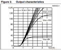
Maybe using only one would be ok because the typical output is around 12V, even with only 5mA LED current. But not 100% sure. This is the output characteristic of the 2nd IGBT type:
1711725500912.png
It looks like the that the voltage loss at about 11A does not really change if driving the gate with 12V instead of 15V.

Rework your Gate-Speed-Up-Circuit to provide a ~30mA, or even up to a ~50mA start-up-boost.
This will substantially speed-up the turn-on-time and reduce HEAT generation on start-up.
It might not be a bad idea to add a single small Transistor to drive the 2 LEDs,
and then reverse the Output-Polarity of the GPIO-Pin.
If You don't want to reverse the GPIO-Output-Polarity,
use 2 small Transistors to correct the Polarity, and drive the 2 LEDs.
Continuous "On" LED-Current should preferably be ~10mA for both LEDs.
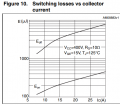
Regarding the spec, the switching time varies a lot about the load capacitance and LED current (more the turn-on time, the turn-off time is more constant). The IGBT has a gate charge of 27nC at Ic=30A and Vge=15V which will be around 2.200pF. The opto driver spec showing a turn-on speed around 2ms with 5mA LED current ant 1ms at 10mA LED current.

1711727348589.png ......1711727388384.png

I'm not sure if I'm able to calculate the turn-on switching loss. I found the turn-on switching energy of the IGBT is about 180µJ at Ic=10A. So even with only 5mA LED current (2ms switching time), the switching power loss would be extremely low... but I'm not sure if I fully understand this ...
1711728288214.png
Still hoping to drive the opto driver LED's just from the GPIO output (I have not found a difference if using the ESP32 GPIO's in positive or negative logic - it seems the same max. current could be used - I can vaguely remember that there are other micro controllers which are able to drive more current in low state compared to high state - but I'm flexible about the LED output logic anyway).
 

Thread Starter

fmeili1

Joined Mar 27, 2024
7
To ask the obvious question - does the solar charge controller not have a "disable" input that you could use to switch the PV off?
Here is a bit of the background of this idea (long story if you are interested in...):

Some of the (low budget) all in one (AIO) off-grid solar inverter/chargers which are non-isolated, high frequency transformerless, don't have a manual PV disconnect switch integrated. They also miss often integrated PV ground fault protection (GFP) and PV arc fault protection (AFP), like mine. Most of these AIO's follow a common similar design (Voltronic clones). One of the drawback of this design is, that the integrated solar MPPT charge controllers are non-isolated from the inverter's AC output due to the PWM sinewave switches which connects them to the internal high voltage DC bus - in fact, the PV input contacts of these MPPT chargers will have high voltage even if no solar panel is connected - the PV voltage will put on top of this (it "rides" on top of the internal AC-ripple)! So no grounding is allowed for either PV- (or PV+) because they are floating.

I'm driving my (200A service) house with 6 of these units running in parallel 240V/120V US split phase setup. Each unit includes a 6500W inverter 120V, two 4000W MPPT charge controller and they are able to charge the solar batteries also from the grid with 6500W (in case the batteries have low SOC and no solar production). All together they have a max. continuous power of 39kW, could handle 48kW of solar input with max. 12 separate PV strings (2 per unit) and I run a 60kW LFP battery with this setup. Currently I'm using 8 PV strings in a range of 200-300VDC and all deliver max. 11A.
These units are available for about $1300 each - so it's an unbeatable price for the power rating - but some safety features are missing because of that (even the are UL listed).

High voltage PV ARC faults are dangerous and the most reason for PV related fires!

So, I think about building an external PV safety circuit which will detect GF and AF via an ESP32 controller (the AF detection is the challenge and will be done with the power spectrum density (PSD) which will be calculated out of the power spectrum via FFT - this scholar article describes the background). If the controller will detect either an AF or and GF, it should switch off the PV string. The GF detection will be done by measuring the current in the PV+ wire and the PV- wire separately via 1 miliOhm shunts and if the current differs, a GF should be detected. The AF detection will just use one of the current measurements and the CPU power may be enough to calculate the spectrum for all 8 strings in parallel because the required resolution is not very high. The ESP32-DevKitC module have enough ADC's to measure all 16 currents for all my 8 strings and it has enough GPIO pins to drive 8 IGBT's to switch the PV strings off in case if an error is detected. The ESP32 has integrated WiFi so I can transfer all measurements and current status via MQTT to my existing smart home system for further monitoring/processing/alerting.

I was very precise and careful while installing everything to prevent safety issues (torque to spec, perfect crimps, enough wire diameters, quality connectors, megger measured the insulation of each PV module with 1000V before installation, added a module based PV rapid shutdown system (Tigo), installed smoke and heat detectors over the AIO's and batteries, etc.). But I would feel better if I would add a GF and AF protection for the PV side - all the PV wires and connectors are exposed to the elements and I live in the Mohave desert with sometimes >125°F (>52°C) in the shade...

Because I already have a PVRSS (Tigo) which is already integrated in my smart home system, I would be able to switch the PV off via this existing feature. So in this case, just a detection of a GF and AF would be enough and the disconnect could be done with the existing PVRSS - but I thought to make the circuit more universal (so others may use it also) so I've planned to add this PV disconnect IGBT in my circuit design. Also the smart home with it's rule engine may fail (runs on a mini PC), so to integrate the detection and disconnect logic in a separate micro controller makes it more reliable - which is good for a safety device.

What are the unspecified reasons it cannot be switched on the negative?
I think there is now reason to switch the negative. But because it's a floating design without ground reference, I think it's no difference if switching the PV+ or PV- with an IGBT (but not sure).

If you add a charge pump or anything that is referenced to ground, then it will ground-reference the solar, so the only solution is @LowQCab 's photovoltaic driver.
Independent of ground reference or not, or using high side or low side IGBT's, I love the idea of these opto drivers because they reduce the required components a lot, it's cheaper and automatically fully insulated, easier PCB layout, etc.
 

Ian0

Joined Aug 7, 2020
10,293
Here is a bit of the background of this idea (long story if you are interested in...):

Some of the (low budget) all in one (AIO) off-grid solar inverter/chargers which are non-isolated, high frequency transformerless, don't have a manual PV disconnect switch integrated. They also miss often integrated PV ground fault protection (GFP) and PV arc fault protection (AFP), like mine. Most of these AIO's follow a common similar design (Voltronic clones). One of the drawback of this design is, that the integrated solar MPPT charge controllers are non-isolated from the inverter's AC output due to the PWM sinewave switches which connects them to the internal high voltage DC bus - in fact, the PV input contacts of these MPPT chargers will have high voltage even if no solar panel is connected - the PV voltage will put on top of this (it "rides" on top of the internal AC-ripple)! So no grounding is allowed for either PV- (or PV+) because they are floating.

I'm driving my (200A service) house with 6 of these units running in parallel 240V/120V US split phase setup. Each unit includes a 6500W inverter 120V, two 4000W MPPT charge controller and they are able to charge the solar batteries also from the grid with 6500W (in case the batteries have low SOC and no solar production). All together they have a max. continuous power of 39kW, could handle 48kW of solar input with max. 12 separate PV strings (2 per unit) and I run a 60kW LFP battery with this setup. Currently I'm using 8 PV strings in a range of 200-300VDC and all deliver max. 11A.
These units are available for about $1300 each - so it's an unbeatable price for the power rating - but some safety features are missing because of that (even the are UL listed).

High voltage PV ARC faults are dangerous and the most reason for PV related fires!

So, I think about building an external PV safety circuit which will detect GF and AF via an ESP32 controller (the AF detection is the challenge and will be done with the power spectrum density (PSD) which will be calculated out of the power spectrum via FFT - this scholar article describes the background). If the controller will detect either an AF or and GF, it should switch off the PV string. The GF detection will be done by measuring the current in the PV+ wire and the PV- wire separately via 1 miliOhm shunts and if the current differs, a GF should be detected. The AF detection will just use one of the current measurements and the CPU power may be enough to calculate the spectrum for all 8 strings in parallel because the required resolution is not very high. The ESP32-DevKitC module have enough ADC's to measure all 16 currents for all my 8 strings and it has enough GPIO pins to drive 8 IGBT's to switch the PV strings off in case if an error is detected. The ESP32 has integrated WiFi so I can transfer all measurements and current status via MQTT to my existing smart home system for further monitoring/processing/alerting.

I was very precise and careful while installing everything to prevent safety issues (torque to spec, perfect crimps, enough wire diameters, quality connectors, megger measured the insulation of each PV module with 1000V before installation, added a module based PV rapid shutdown system (Tigo), installed smoke and heat detectors over the AIO's and batteries, etc.). But I would feel better if I would add a GF and AF protection for the PV side - all the PV wires and connectors are exposed to the elements and I live in the Mohave desert with sometimes >125°F (>52°C) in the shade...

Because I already have a PVRSS (Tigo) which is already integrated in my smart home system, I would be able to switch the PV off via this existing feature. So in this case, just a detection of a GF and AF would be enough and the disconnect could be done with the existing PVRSS - but I thought to make the circuit more universal (so others may use it also) so I've planned to add this PV disconnect IGBT in my circuit design. Also the smart home with it's rule engine may fail (runs on a mini PC), so to integrate the detection and disconnect logic in a separate micro controller makes it more reliable - which is good for a safety device.


I think there is now reason to switch the negative. But because it's a floating design without ground reference, I think it's no difference if switching the PV+ or PV- with an IGBT (but not sure).


Independent of ground reference or not, or using high side or low side IGBT's, I love the idea of these opto drivers because they reduce the required components a lot, it's cheaper and automatically fully insulated, easier PCB layout, etc.
Thank you. I'm always interested to learn about the advantages and disadvantages of various off-gird products. I work with Victron products. Their MPPTs are buck regulators (non isolated), and have a handy volt-free-contact input to shut them down: their inverters are isolated because it is a DC full-bridge at 48V feeding a 50Hz transformer.
 

Thread Starter

fmeili1

Joined Mar 27, 2024
7
Thank you. I'm always interested to learn about the advantages and disadvantages of various off-gird products. I work with Victron products. Their MPPTs are buck regulators (non isolated), and have a handy volt-free-contact input to shut them down: their inverters are isolated because it is a DC full-bridge at 48V feeding a 50Hz transformer.
I really like Victron products (I'm using them in my motorhome) but for my required power, Victron was way over my budget. Victron does not offer a AIO's. So it would have required many separate MPPT chargers (Quattro's with high PV voltage) for 8 strings on top of the inverters (max. 5kW inverters for US split phase are available from Victron) + Gerbo, shunt etc.
It took me a while to think about it before I've decided to go with the cheap option - with all possible pitfalls like inverter noise and cooling, etc... but the price was the decision driver because the target was to drive the whole house completely from solar with batteries - always!
I maybe need 3-5 days per year for a few hours to auxiliary charge a bit from the grid (we have about >300 complete sunny day's per year here). Our city code does not allow to be completely disconnect from the grid, so it's there anyway.

Here is a picture of the system:
20231220_070402.jpg
 
Top