4511 ic and common anode 7 seg display

Thread Starter

Danger Mouse

Joined Nov 6, 2016
4
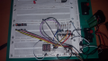
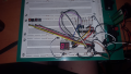
So, I bought myself a couple of 4511 chips intent on running a dual 7 segment display. Halfway through wiring it up on a breadboard and I realise, this is a common anode display. I hadn't pinned it out prior to buying the chips. Is it at all possible to use the 4511 chips to drive it or am I (as I expect) out of luck and due another trip to the component store?

And to confirm my reasoning, I found that with the positive terminal of a battery connected to one pin I could illuminate different segments by touching the pins with the negative terminal of the battery - so this means it is common anode yes? Super noob here, with salvaged parts, I know how to have a good time :D
 

MrChips

Joined Oct 2, 2009
30,712
1. Don't connect any LED to battery or power source directly. Make sure you put current limiting resistors in series.
2. So you found out that 4511 drives common cathode seven-segment displays. That is what you need to buy.
3. You can either change the display to common cathode or you can change the driver chip.
4. It depends on the rest of the circuitry that is driving the 4511. Are you using TTL or CMOS chips in the overall design? If you are using TTL, 74LS47 will drive common anode displays.
5. If you want to get something working temporarily until your next trip to the store, use inverter gates, chips or transistors between the seven output pins of the 4511 and the cathodes of the seven-segment display.
6. Make sure you use current limiting resistors, 470Ω to 1kΩ, one each on each of the seven segments.
 

Thread Starter

Danger Mouse

Joined Nov 6, 2016
4
Oh I forgot to mention, I had a lm317 starring in a variable current circuit set up for LED testing, quite chuffed with the little 2ma-26mA circuit, I definitely should have mentioned that. Good advice though, after blowing two the other day I looked up a solution, definitely don't just plug stuff in and hope for the best (even if you have a resistor in there, it has to be the RIGHT resistor, my bi-coloured LED's died so no one else's have to!)

As for the rest of the circuit, well it seems I don't have a BCD counter lying around, I have a 4017. Definitely need another trip to the shop to go forward. I will however have a play around with some transistors because that looks like the answer I'm looking for today - inverter gates. I impulsively got the 4511 when I was picking up some stuff for my housemate (50/50 on what an unknown display would be and I lost the gamble), so I guess I'll see how I go having fun with that and actually plan my purchase next time!

Thank you for your help though, it means I have more to do with this display before giving up today! Thanks again! (and I'm following an application circuit so I'm already using using all the 470resistors, a couple of 360ohm and 110ohm in series at two pins, and took a forum break before hunting for any 1k's because those are like hens teeth around here - yes, resistor packs are on my next shopping trip's list too! Good advice though, never underestimate the devastation you can wreak when you overlook resistors!)
 

Thread Starter

Danger Mouse

Joined Nov 6, 2016
4
Well! Looking at my handiwork I figure SURELY this can't actually work.. .
and yet...
! I'm counting in two's, have missed the odd numbers somehow... but I'll take half the numbers over none any day! Switch 1 displays 2, switch 2 displays 4, switches 1 and 2 together displays 6 and switch 3 displays 8. Switch 4 resets (blank) then displays 0 again. It's a start! One common anode display running off a 4511 with the help of some transistor NOT gates :D
 

Attachments

Dodgydave

Joined Jun 22, 2012
11,285
If you have already got common Anode leds, you can use a Cd40106 hex inverter to drive the segments with a Cd4511 chip, otherwise use common Cathode leds.
 
Top