Facebook
 Google
 GitHub
 Linkedin
Hi
I wonder if there are any experts out there that could help me with my driver output stage. I am building coil drivers for medical bug killers but I am an amateur when it comes to switch mode type output stages because the closest I came to switch modes at university was in the power supply of the main frame that use to run my Algol batch programs.
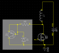
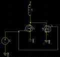
As you can see from the attached schematics I started with a single ended driver but as I pushed up the current to now 150A in to the coil the diode across the load has turned in to a 4 cube heat sink where the massive stud diode and a series 100 W resistor are mounted. So I thought why not use a second MOSFET and just get it to effectively short out the coil to dump the stored inductor energy to replace the diode contraption. At the moment the new drive circuit is switching 40A on 5V and works better than I expected. Looking at the drive wave forms and output switching speeds I decided that dead bands were not required although there is one anomaly that can be seen in the scope picture. The spike causes the upper transistor to heat more than the lower one. In fact I should say the upper transistor heats and the lower one doesnt. I have tried a diode across the load figuring it must be the back lash from the coil but it made no difference to the spike. I would be grateful for any opinions about what the cause might be and the best way to fix it.
The circuit has been running for several weeks with no problems and the spike is actually beneficial for the application on 5V allowing the coil to be switched up to 2 MHz at 40A giving 5 times the voltage and energy at the front end of the wave. However I wish to increase the voltage to push more current and the transistors are limited to 25V so the heating of the upper transistor will be too great and the voltage of the spike would kill the transistors hence the need to stop the spike.
Thanks
I wonder if there are any experts out there that could help me with my driver output stage. I am building coil drivers for medical bug killers but I am an amateur when it comes to switch mode type output stages because the closest I came to switch modes at university was in the power supply of the main frame that use to run my Algol batch programs.
As you can see from the attached schematics I started with a single ended driver but as I pushed up the current to now 150A in to the coil the diode across the load has turned in to a 4 cube heat sink where the massive stud diode and a series 100 W resistor are mounted. So I thought why not use a second MOSFET and just get it to effectively short out the coil to dump the stored inductor energy to replace the diode contraption. At the moment the new drive circuit is switching 40A on 5V and works better than I expected. Looking at the drive wave forms and output switching speeds I decided that dead bands were not required although there is one anomaly that can be seen in the scope picture. The spike causes the upper transistor to heat more than the lower one. In fact I should say the upper transistor heats and the lower one doesnt. I have tried a diode across the load figuring it must be the back lash from the coil but it made no difference to the spike. I would be grateful for any opinions about what the cause might be and the best way to fix it.
The circuit has been running for several weeks with no problems and the spike is actually beneficial for the application on 5V allowing the coil to be switched up to 2 MHz at 40A giving 5 times the voltage and energy at the front end of the wave. However I wish to increase the voltage to push more current and the transistors are limited to 25V so the heating of the upper transistor will be too great and the voltage of the spike would kill the transistors hence the need to stop the spike.
Thanks
Attachments
-
 7.5 KB Views: 73
 -
 6.1 KB Views: 59
 -
 59 KB Views: 46
 ). I 'll have to fix that before testing if the cap will solve the spike problem.