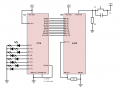
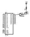
4040 and 2716 EPROM; is this the way to set it up?

Thread Starter

georgedb

Joined Jul 29, 2017
49
I wanted to make, solely as a test, this 2716 EPROM reader. This EPROM only needs +5V, where a 2708 uses various voltages. Reading a 2708 will be the next step, then programming it (with a high voltage on VPP, depending on the datasheet between 12,5, 21-27V)...

I just wanted to check with you if what I designed is alright. In fact, I hooked it up and it worked for 99.5%. Then I took it apart (it was on a breadboard) and made the attached schematic from the top of my head.

I wouldn't have any doubt, if for some odd reason some addresses, which I generated with pulsing the 4040, did not result in output LED's (which do have resistors!) that were representing a zero, lighting up very dimly... I can't imagine what I'm doing wrong here. It was only a few addresses where I could see that: LED's on, LED's off (perfect so far) and very, very few times a LED that that was barely visibly lit.

I'm using 5V LEDs with build-in resistors, but these typically consume around 13mA; I have no idea if a 2716 can handle that (well it could, it is still alive). If (officially) not, then the only solution would be to use 8 transistors?

Another next step would be to display both nibbles of the byte read in the EPROM on an LED display (0-9, A-F). Is there any 4000-CMOS or 74XX TTL IC specifically for that purpose?
 

Attachments

MrChips

Joined Oct 2, 2009
35,273
You have a number of problems with your design.

1) All 2716 are not the same. You have to look at the part number on the IC and check the datasheet for proper device operation.

2) In general, logic devices do not supply enough current to drive LEDs connected to GND. You need a buffer that will sink current from Vcc through a resistor connected in series with the LED.

3) Your push-button to step the address register need to be debounced. The circuit you have shown is not good enough to prevent multiple clocking.
 

dl324

Joined Mar 30, 2015
18,490
I have no idea if a 2716 can handle that (well it could, it is still alive). If (officially) not, then the only solution would be to use 8 transistors?
That's what datasheets are for.
STM:
upload_2018-10-23_9-40-45.png
upload_2018-10-23_9-41-12.png

2716 is NMOS, can't source any appreciable current. You could use CD4049 to drive LEDs.

Another next step would be to display both nibbles of the byte read in the EPROM on an LED display (0-9, A-F). Is there any 4000-CMOS or 74XX TTL IC specifically for that purpose?
There used to be some (MC14495, ...), but virtually unobtanium now. Your best bet is to use a small programmable memory (32x8 PROM, etc) and make a look up table. MC14495 was ROM based.

What's the point of your circuit? Single stepping through 2k addresses would be tedious. If you just want to blink some LEDs, add an oscillator and let it increment addresses.
 

Thread Starter

georgedb

Joined Jul 29, 2017
49
You have a number of problems with your design.

1) All 2716 are not the same. You have to look at the part number on the IC and check the datasheet for proper device operation.
True, with these old parts there are all kinds of variants (especially in programming voltages!)
2) In general, logic devices do not supply enough current to drive LEDs connected to GND. You need a buffer that will sink current from Vcc through a resistor connected in series with the LED.
That is not completely clear to me, do you maybe have piece of schematic that illustrates how to wire things?
3) Your push-button to step the address register need to be debounced. The circuit you have shown is not good enough to prevent multiple clocking.
Do you have a suggestion or example to improve it? The capacitor is 10nF currently, and seems to do its debouncing job, but apparently there is a better way. I hope you can let me know.
 

Thread Starter

georgedb

Joined Jul 29, 2017
49
True ;-) However, what you're showing here, is that the relevant part of the datasheet to see what the maximum current is? It looks like a sort of test condition in relation to the output voltages for the states Low and High, or am I mistaken?
2716 is NMOS, can't source any appreciable current. You could use CD4049 to drive LEDs.
Thank for the hint, I'll lookup the datasheet.
There used to be some (MC14495, ...), but virtually unobtanium now. Your best bet is to use a small programmable memory (32x8 PROM, etc) and make a look up table. MC14495 was ROM based.
Thanks for the hint! Easy to find, approx USD 1 a piece on Ebay...
What's the point of your circuit? Single stepping through 2k addresses would be tedious. If you just want to blink some LEDs, add an oscillator and let it increment addresses.
It was actually just to learn from it. Next step is testing a 2708 (somewhat more complicated), then hooking it up to an Arduino to be able to dump a ROM and the last step is to actually program a 2708, also via an Arduino. Timing for the programming pulses might be the biggest challenge.
 

Thread Starter

georgedb

Joined Jul 29, 2017
49
3) Your push-button to step the address register need to be debounced. The circuit you have shown is not good enough to prevent multiple clocking.
Another problem might be that counting does not start at zero, but at address one, might this be due to the capacitor over the switch?
 

dl324

Joined Mar 30, 2015
18,490
True, with these old parts there are all kinds of variants (especially in programming voltages!)
Just pay attention to the part numbers. 2716 are VPP=25V, 2716A are VPP=21V, and 2716B are VPP=12V.
That is not completely clear to me, do you maybe have piece of schematic that illustrates how to wire things?
upload_2018-10-23_12-53-38.png
With a 5V supply, CD4049 can sink several mA. For more, you can use ULN2003 or discrete transistors.
 

dl324

Joined Mar 30, 2015
18,490
True ;-) However, what you're showing here, is that the relevant part of the datasheet to see what the maximum current is? It looks like a sort of test condition in relation to the output voltages for the states Low and High, or am I mistaken?
Recommended operating conditions.
Thank for the hint, I'll lookup the datasheet.Thanks for the hint! Easy to find, approx USD 1 a piece on Ebay...
I'd think very seriously before buying seemingly hard to get parts, or any for that matter, on eBay. Likely to be counterfeit, particularly if it ships from China. Sellers with odd lots of parts could be more trustworthy, but I've been burned by people repackaging into smaller lots and not knowing about proper handling. I've gotten CMOS IC's with their leads poked into styrofoam; now they're timebombs.
It was actually just to learn from it. Next step is testing a 2708 (somewhat more complicated), then hooking it up to an Arduino to be able to dump a ROM and the last step is to actually program a 2708, also via an Arduino. Timing for the programming pulses might be the biggest challenge.
Unless you absolutely have to use them, 2708 are a waste of time. Use something that's easier to use.

If you're going to try to program with an Arduino, why don't you use it to read the 2716?
 

MrChips

Joined Oct 2, 2009
35,273
2k memory locations is a large number to step through manually.

Why don't you interface the EPROM address and data bits to a parallel port so that you can read all 2k memory directly into a computer.

By doing so, you are almost halfway to creating your own EPROM programmer.
 

Thread Starter

georgedb

Joined Jul 29, 2017
49
Unless you absolutely have to use them, 2708 are a waste of time. Use something that's easier to use.
It is actually to fun to get it working and it is related to some old devices. I could replace a 2708 with another EPROM and rewire the pins, but would like to keep things as original as possible.
If you're going to try to program with an Arduino, why don't you use it to read the 2716?
That's the next step. I don't know a lot about electronics and wanted to start as simple as possible. With an Arduino added, I could create errors in the software, in the connections - therefore I'd like to pick things up step by step and learn from it.
 

Thread Starter

georgedb

Joined Jul 29, 2017
49
2k memory locations is a large number to step through manually.
So true ;-) But this is just an experiment, in a next step I'll use an Arduino.
Why don't you interface the EPROM address and data bits to a parallel port so that you can read all 2k memory directly into a computer.
By doing so, you are almost halfway to creating your own EPROM programmer.
That would indeed make life a lot easier, but then I would need to buy one of these USB to LPT convertors, but I understood that these are meant only for driving a printer and that not all signals are outputted...

You made a remark about my switch debouncing (I used a 10nF capacitor in parallel with the switch). Can you please tell me what a proper switch debouncing circuit would look like?
 

Thread Starter

georgedb

Joined Jul 29, 2017
49
Apart from the debouncing circuit and the buffering of the LED's (I have a ULN2803 lying around, that should do the job), I still got 2 challenges, hope you can help me with these:
  1. I'm still searching for an explanation why an "off" LED lights up very dimly? Now it is an LED (harmless), if it were the input to another chip, it might turn things completely upside down (from a functional point of view);
  2. How can I avoid that counting seems to start at 1, so before I pushed the button for the first time? What you'd like here, is some sort of a reset of the MR line of the 4040 upon powering up. This must be a generic problem, but I have not found a way to solve it. Upon powering up, all circuits should reset.

I hope you can help me with this.
 

dl324

Joined Mar 30, 2015
18,490
I'm still searching for an explanation why an "off" LED lights up very dimly? Now it is an LED (harmless), if it were the input to another chip, it might turn things completely upside down (from a functional point of view);
Measure the voltage of an output with a dim LED and see if that tells you anything. 4 decades ago, leaky LEDs weren't uncommon, but should be uncommon of now.
How can I avoid that counting seems to start at 1, so before I pushed the button for the first time? What you'd like here, is some sort of a reset of the MR line of the 4040 upon powering up. This must be a generic problem, but I have not found a way to solve it.
I can't think of any counter that's guaranteed to power on with a count of zero. That's why they have a reset input or an option to preset zero.
Upon powering up, all circuits should reset.
You have to make that happen.
 

MrChips

Joined Oct 2, 2009
35,273
The best way to create a clean clock pulse from a pushbutton is to use SPDT pushbutton switch. They are not readily available but you can find them. The implementation will depend on the logic family of the gates chosen.


MrChips

Joined Oct 2, 2009
35,273
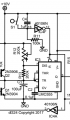
Here are two simple ways to reset the CD4040 chip that requires a logic HI to reset.

The drawing on the left is a POWER ON RESET.
The drawing on the right is a manual reset using a pushbutton.


dl324

Joined Mar 30, 2015
18,490
The duration of the desired power on reset determines the component values. This is a circuit I've used:
upload_2018-10-24_10-29-28.png
C4, R11, and IC4F are the power on reset.
 

Thread Starter

georgedb

Joined Jul 29, 2017
49
@dl324 and @MrChips: thanks so much, this is really, really helpful.
I learned a lot through this thread and can resuse these "snippets" in many digital circuits, which improves my experimenting!
Thnx!
 

dendad

Joined Feb 20, 2016
4,642
Just a note on programming 2708 chips. Make sure you are familiar with the programming as that cannot be programmed in one go like the 2716 chips, but must have multiple part programming runs otherwise you destroy the chip.
I think my programmer looped through with short programming pulses 256 times if my memory is correct. Where as the 2716 just has a single programming run.
 

Thread Starter

georgedb

Joined Jul 29, 2017
49
Just a note on programming 2708 chips. Make sure you are familiar with the programming as that cannot be programmed in one go like the 2716 chips, but must have multiple part programming runs otherwise you destroy the chip.
I think my programmer looped through with short programming pulses 256 times if my memory is correct. Where as the 2716 just has a single programming run.
Thanks for your remark! Especially for programming and especially for the awkward 2708: the datasheet is leading. It is indeed about:
  • Voltage level
  • Duration of a pulse
  • Number of pulses
Without the datasheet, there is a big chance to destroy an EPROM.
 
Top