 Facebook
 Google
 GitHub
 Linkedin
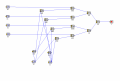
This is my 4 to 1 Multiplexor circuit but I need help because it isn't right. Does anyone know what I'm doing wrong? It has to be in Simcir.
Attachments
-
 302.6 KB Views: 11
| Thread starter | Similar threads | Forum | Replies | Date |
|---|---|---|---|---|
|
|
Multiplexor analog readings problem | Digital Design | 43 | |
| Y | Another name for multiplexor | Homework Help | 2 | |
|
|
Which multiplexor to use? | Digital Design | 1 | |
| R | 4 to 1 multiplexor | Homework Help | 2 | |
| K | Solid state multiplexor for microvolt-level signal | Digital Design | 2 |


