3pin to 2pin switch question

Thread Starter

Bliepbliep

Joined May 16, 2018
12
Hello
I'm a electronics noob so forgive me if I ask a stupid question.
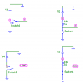
I have a momentary switch that has standard 3 pins

When the switch is off (not pressed)
Circuit is closed between pin 1 and 2
When the switch is pressed the pins between 1 and 2 are open
And 2 and 3 are closed.

Now my question is: Is it possible to simulate this behavior with a 2 pin switch?
 

DECELL

Joined Apr 23, 2018
96
Hi,
I suppose it depends on what you need the switch to do? If you want to switch power supplies, then no. This spdt form alternately connects pin 2 to 1 or 3. Lets say you want to connect pin 2 to either 0V or 5V, then pin 1 is 0V and pin 3 is 5V.
You an get the same effect using a pull up resistor and a spst swtich. upload_2018-5-16_11-20-11.png
 

Attachments

Thread Starter

Bliepbliep

Joined May 16, 2018
12
sorry for my late reply

Switch is used on a control unit
It's a 3pin switch
In switch off position pin 1 and 2 are closed (3 is open)
If switch is pressed (on) pin 2 and 3 are closed (1 is open)

So my guess is that pin 2 is ground.

It switches a 5 or 12v signal
Control unit knows when 1 and 2 or 2 and 3 are closed or open.

I want to simulate this with a 2 pin switch.

I hope this information helps.
 

jpanhalt

Joined Jan 18, 2008
11,087
The equation you need is called Ohm's law: E= IR (E= volts, I = current, A, R = resistence, ohms);

So, 12V/10x10^3 ohm = 1.2x10^-3 A (1.2 milliamps)
Power dissipated (W) = I^2 x R
So, (1.2X10⁻³)^2 x 10x10^3 =0.0144 W. Thus, a 1/4 W resistor (0.25W) will do.

Those are equations worth learning. You will use them many times.
 

AnalogKid

Joined Aug 1, 2013
12,077
So my guess is that pin 2 is ground.
Not automatically. Please post a schematic or wiring sketch showing the signals connected to each pin and indicating which are inputs and outputs. I think I know what you are trying to ask, but not sure yet.

Where are you located?

ak
 

Thread Starter

Bliepbliep

Joined May 16, 2018
12
It's working like this.
Original switch is a 3 pin switch
When the switch is not pressed.
Pin 1 and 2 are connected

When the switch is pressed
Pin 1 and 3 are connected


BobTPH

Joined Jun 5, 2013
11,480
Yes, you can use the SPST switch to power an SPDT relay.

If you could show us how the switch is used in the circuit, there may well be other ways to do it without a relay.

Bob
 
Last edited:

AnalogKid

Joined Aug 1, 2013
12,077
To ground one of two separate control lines while keeping them isolated from each other at all times is not possible with only a SPST switch.

ak
 
Last edited:

BobTPH

Joined Jun 5, 2013
11,480
To ground one of two separate control lines while keeping them isolated from each other at all times is not possible with a SPST switch.

ak
Perhaps you should qualify that with “using no other components”

There are plenty of ways with additional components.

Bob
 

AnalogKid

Joined Aug 1, 2013
12,077
Perhaps you should qualify that with “using no other components” There are plenty of ways with additional components.
True, but none of the posts from the TS imply (to me) that other components are an option. And, we don't know what the "control" signals are.

ak
 
Top