36 volt DC battery indicator on a 24 volt system

MrChips

Joined Oct 2, 2009
31,195
You need to try and do the reverse engineering yourself.
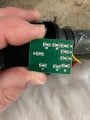
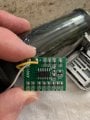
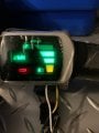
LM339 is a quad analog comparator that outputs to four LEDS.
There will be five resistors in series. Try to draw these five resistors and label the values.
All you will need to do is identify the top resistor and then change that (or add another resistor in parallel) to change the range from 36V to 24V.

The circuit will be similar to this:

1719697678371.png
 

MrChips

Joined Oct 2, 2009
31,195
Notice that resistor R3 is missing. I cannot see how this would work for 36V range.
A voltage divider is created with 130kΩ to +V and R3 to GND. The FULL reference voltage threshold is set at 2.5V
You will have to do some experimenting with this. Try with a 15kΩ resistor where it shows R3. This will give 2.48V when the battery voltage is 24V.

Edit: I think I can see it now. There is a resistor with marking code 7321 at the lower right corner. I am going to assume that this is the lower arm of the voltage divider. You can check with an ohmmeter to see if this is in parallel with R3. If it is, then remove 7321 and put the 15kΩ resistor in its place or in position R3.

1719706882613.png
 

Thread Starter

samsonboxer

Joined Jun 28, 2024
14
Notice that resistor R3 is missing. I cannot see how this would work for 36V range.
A voltage divider is created with 130kΩ to +V and R3 to GND. The FULL reference voltage threshold is set at 2.5V
You will have to do some experimenting with this. Try with a 15kΩ resistor where it shows R3. This will give 2.48V when the battery voltage is 24V.

Edit: I think I can see it now. There is a resistor with marking code 7321 at the lower right corner. I am going to assume that this is the lower arm of the voltage divider. You can check with an ohmmeter to see if this is in parallel with R3. If it is, then remove 7321 and put the 15kΩ resistor in its place or in position R3.

View attachment 325822
You know when you said that this shouldn’t work on the 36V range you are correct. I thought before I put in the resistor I would test with a 40V battery. As you can see the display on the throttle only reads 1/4 at 40V. This offshore junk is very frustrating!
 

Attachments

MrChips

Joined Oct 2, 2009
31,195
That sounds about right.
Your reference levels are
2.50 V
2.36 V
2.22 V
2.08 V

The voltage divider resistors now are,
R1 = 130k Ω
R2 = 7.32k Ω
Vin = 41.4 V
Vout = Vin x R2 / (R1 +R2) = 41.4 x 7.32 / 137.32 = 2.21 V ±2%

1719786007381.png
 

Thread Starter

samsonboxer

Joined Jun 28, 2024
14
That sounds about right.
Your reference levels are
2.50 V
2.36 V
2.22 V
2.08 V

The voltage divider resistors now are,
R1 = 130k Ω
R2 = 7.32k Ω
Vin = 41.4 V
Vout = Vin x R2 / (R1 +R2) = 41.4 x 7.32 / 137.32 = 2.21 V ±2%

View attachment 325884
Update I remove 7321 and put the 15kΩ resistor in its place and now have 3/4 power (see attached photo) on 24 volts. Any idea how I can get to 100% on the indicator?
 

Attachments

MrChips

Joined Oct 2, 2009
31,195
R1 = 130k Ω
R2 = 15k Ω
Vin = 24 V
Vout = 24 x 15k / 145k = 2.48 V

We need to get above 2.5 V.
R2 = 16k Ω should do it.

R1 = 130k Ω
R2 = 16k Ω
Vin = 24 V
Vout = 24 x 16k / 146k = 2.63 V

Note however, a fully charged 24 V battery could very well be about 26 V which would give 2.69 V with the 15k Ω resistor.
25 V input would give 2.59 V.
 

Thread Starter

samsonboxer

Joined Jun 28, 2024
14
R1 = 130k Ω
R2 = 15k Ω
Vin = 24 V
Vout = 24 x 15k / 145k = 2.48 V

We need to get above 2.5 V.
R2 = 16k Ω should do it.

R1 = 130k Ω
R2 = 16k Ω
Vin = 24 V
Vout = 24 x 16k / 146k = 2.63 V

Note however, a fully charged 24 V battery could very well be about 26 V which would give 2.69 V with the 15k Ω resistor.
25 V input would give 2.59 V.
Ok great will try what you suggest and fingers crossed I won’t bother you anymore.
R1 = 130k Ω
R2 = 16k Ω
 

Thread Starter

samsonboxer

Joined Jun 28, 2024
14
No problem. I am here to help you with any problem you might encounter with this.

You may want to know at what voltage the orange light goes on/off. It is around 20 V.
I’m having issues finding a 16K 0805 SMD locally. I’m in Vancouver Canada and any components must be ordered online. The 130K I can get. How critical is it that i go from 15K to 16K?
 

MrChips

Joined Oct 2, 2009
31,195
You have a number of options:

1) Firstly, you need to test that in fact the 15k Ω is the correct value to use for a 25-26V battery.

2) Resistors are made in standard values known as E6, E12, E24, etc.
16k is available in the E24 series.

https://www.logwell.com/tech/components/resistor_values.html

3) You don't need an exact value. You can get close enough by putting two resistors in series, e.g. 15k + 1k, 10k + 5.6k, or 7.5k + 8.2k.

4) For SMD resistors, it is easy to stack two resistors in parallel if vertical space permits, for example, two 33k in parallel gives 16.5k, 33k in parallel with 30k gives 15.7k.

I suppose you can buy one resistor. It is more cost effective to buy in large quantities. I usually buy resistors in quantities of 100. But I am in the electronics business.

(Edit: Newark has no shipping charges.)
 
Top