Facebook
 Google
 GitHub
 Linkedin
hi guys
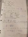
Does anyone on here have a mathematical example of how the 3 wire RTD when connected to a Wheatstone bridge cancels out the lead wires.
I am new to all this and have just got an understanding of the theory on the Wheatstone bridge and how through changing a resistor we can work out what the RTD resistance is.
When I put in the lead wire resistances (these are just made up for the sake of doing the equation) I can't seem to see how they are cancelled out)
I like to understand things in depth and have watched every you tube clip and looked at almost every web page but can't find the answer I want. Everyone gets to the point of showing the diagram to wire in the RTD. But no one actually does it mathematically. By showing a Wheatstone with resistances before worked out then after the lead resistances are added in. If I could see this, I could see where I'm going wrong.
Please don't tell me that just because one lead is in one fraction of the circuit and one in the other fraction that they are cancelled out. That doesn't make sense to me in the fact that one of those leads would still affect the variable resistor ratio.
have been using Rx=R3x(R2/R1) but I'm opening to the other variations of ohms law.
thank you.