 Facebook
 Google
 GitHub
 Linkedin
hello everyone
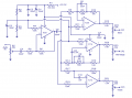
I'm trying to make a 3 channel active crossover circuit based on LF353. I got a circuit diagram from the web but have a doubt regarding the connections. I would like to know that whether there is a connection between the middle point of R2 & R3 (each of 10k) resistor with capacitor C3 (100uF) because in all the other places in the circuit the connection is either jumped to represent no connection & a dot to represent a connection. Here nothing is given,so I'm little bit confused. I believe that there is a connection between R2, R3 & C3 to act as a voltage divider for C3 elsewhere the resistors could be combined to represent a 20k resistor but i want to make sure that I'm right. Could anyone give help me out??
I'm trying to make a 3 channel active crossover circuit based on LF353. I got a circuit diagram from the web but have a doubt regarding the connections. I would like to know that whether there is a connection between the middle point of R2 & R3 (each of 10k) resistor with capacitor C3 (100uF) because in all the other places in the circuit the connection is either jumped to represent no connection & a dot to represent a connection. Here nothing is given,so I'm little bit confused. I believe that there is a connection between R2, R3 & C3 to act as a voltage divider for C3 elsewhere the resistors could be combined to represent a 20k resistor but i want to make sure that I'm right. Could anyone give help me out??
Attachments
-
 46 KB Views: 23


