Facebook
 Google
 GitHub
 Linkedin
Hi all
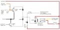
I am wanting to build a module that can be controlled by 3 different inputs.
This will be used in my car to supply a 12vdc (13.8vdc max) 10 amp output to my aftermarket electronics.
I have stated that there are 3 inputs. BUT only ONE input out of the 3 will be used during the life of this circuit. I do not know which style of input will suit my needs till I actually try this in the real world. So I am wanting to prepare for worst case scenario and be ready to use ANY of the inputs to activate my 10 amp output relay, as indicated on my diagram.
I also will be using the negative 1 Amp 12vdc ground output to power up to 2 external standard 12v relay for the life of this circuit.
I have a 3 pin selector jumper to prevent feedback to the 7805 regulator, in case I only use 5v MCU triggered input.
I have attached my diagram circuit for feedback and verification that this circuit will work.
Thank you so much for any info/guidance that you can give me.
TONY
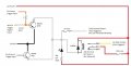
Attachments
-
 80.3 KB Views: 139
")