3.0V CMOS Coin battery booster to 5V, 300mA

Thread Starter

Exjay

Joined Nov 19, 2015
196
Yes, I get you want the user to specify the words, but you have to say how each character looks... so, for example, is the font based on a 5 x 5 bitmap or a 5 x 4 bitmap? For example, in a 5x5 font the character A is represented by the 5 binary values:

00100​
01010​
10001​
11111​
10001​

while in a 5x4 its:

0010​
0101​
1001​
1111​
1001​

With the former, allowing 1 column between letters you get 3 letters at a time, with the latter you get 3.6 letters at a time

This is a 5x5 monospaced font at 10mS per column (0.5s per character). Monospaced fonts are f-ugly but easy to program...

View attachment 246452

Now consider that, in my proposed solution, each row is energised 5 times between each shift, so each row is on for 2mS in 10mS. Effectively every LED is running at 1/5 max brightness. We can compensate for this to some extent by increasing the current through the LEDs. This will give a consistent brightness across all LED as the multiplexing is at row level and is at a constant frequency irrespective of the number of LEDs switched on.

Now consider your charlieplexing approach where one LED in 90 is switched on. Each LED gets 1/90 of 10mS or 111uS. It doesn't matter what current level you set, you will never really see them on. You might consider breaking it down into 3 groups of 5 x 6 where you charlieplex the 6 and strobe across the 5. Then you need 5 + 3 * 3 = 14 pins but each LED per group of 6 is still only on for 1/30 of of 10mS or 333uS and that's still 1/30 full brightness. Arguably you could charlieplex 3 groups of 30 without strobing but that needs 18 pins and still only gives 333uS per LED. Plus charlieplexing needs the dropper resistors so still wastes battery power.

Charlieplexing is great for static displays where only a few LED are on - eg warning/alarm boards where mostly they are off, or where you have a small number of LED broken into independent non-multiplexed groups. It just doesn't work for your requirements.
Thanks Irving,
You've so helpful.
I have seen tutorials online using arduino and PIC for charlieplexing.
I know get the concept of font and bit map
 

BobTPH

Joined Jun 5, 2013
11,666
Do you get it that with charlieplexing of 90 LEDs they are turned on / off in groups of 10 so each LED is on at most 1/9 of the time?

Which is fortunate for your current requirements, because at most 10 LEDs will be on at once.

With that low a duty cycle, the LEDs will be dim at the rated current, but you can push the current higher to partially compensate.

Bob
 

Irving

Joined Jan 30, 2016
5,195
Do you get it that with charlieplexing of 90 LEDs they are turned on / off in groups of 10 so each LED is on at most 1/9 of the time?

Which is fortunate for your current requirements, because at most 10 LEDs will be on at once.

With that low a duty cycle, the LEDs will be dim at the rated current, but you can push the current higher to partially compensate.

Bob
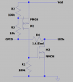
Well TS wanted 2mA per LED. A typical PIC i/o pin is limited to 20mA sink at Vol of 0.5v, so 0.05v @ 2mA, and Vdd-0.5v @ 10mA for Voh or approx Vdd-0.1v @ 2mA; the ON resistance of the lower n-MOSFET is around 25ohm and 50ohm for the upper p-MOSFET and its fairly constant at low currents. As shown here without series resistors, the voltage across the LEDs is > 1.8v; with 1 LED on per row the overall MOSFET on-resistance will limit it to around 15mA, but with 10 LED on per row, each LED will see approx 4mA. The problem here is that the brightness will vary significantly according to the number of LEDs. If you put series resistors on each pin of 330ohm you can only drive 1 LED at a time, but brightness will be more constant. Alternatively a 575ohm per up/down LED pair will maintain a more constant brightness at the expense of 45 resistors and 23mW of wasted energy.
Alternatively an n & p-channel pair (in a SOT23-6 case) as shown below will allow any desired LED current to be set while pulling down with 10mOhm so getting constant and controlled brightness.

1629912489435.png

Having said all that, you've lost simplicity.... plus added significant component count. My original scheme will be considerably cheaper to manufacture and test and will be more reliable.
 
Last edited:

Irving

Joined Jan 30, 2016
5,195
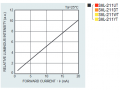
Looking at LED datasheets and picking a likely one from Mouser's catalogue 2mA, 1.8v, 2mcd superbright such as Rohm's SML-211UT, its light output is typically 2.5mcd, but minimum 0.9mcd. To make this work you'll either need to sort LEDs into matched batches of light-output/Vf/If and then chose series resistors per assembled device on test, or get the manufacturer to select & batch for you. Either way, that's a process or an expense you need to account for in your time & cost estimates.

Edit: data-sheet chart showing luminosity v If - its roughly linear, 20mA = 10x the output at 2mA
1629914676349.png
You can buy the LED pre-sorted by luminosity
1629914876157.png
So a -J suffix guarantees 2.5mcd @ 2mA, but doesn't guarantee matching.
 
Last edited:
Top