2N3904 C-E Amp not working

Thread Starter

KLillie

Joined May 31, 2014
137
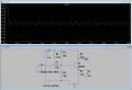
I attached my circuit. Spice says I should have an output. If I change the .1uf emitter cap. to .8uf I get a good swing on spice, but who has an .8uf non-polarized cap? I have an oscillator I built that is feeding the AC signal. Any ideas why I have no output?
 

Attachments

crutschow

Joined Mar 14, 2008
34,452
C2 must be large enough to bypass R2 at the lowest frequency of interest and thus needs to have an impedance below the intrinsic base-emitter resistance Rbe of the transistor. This resistance is about .026/Ie where Ie is the transistor emitter current.

Your transistor is biased at about 0.5mA giving a value for Rbe of about 52Ω.
For a capacitive impedance of less the 52Ω at 4kHz requires a capacitor of >.8μF as you noted. A lower capacitance causes negative feedback from R2, thus causing a reduced gain as you noticed.
0.1μF gives a gain of about 16.

But you can use a polarized (electrolytic) capacitor as the emitter voltage is always positive and never goes below 0V so make C2 at least 1μF.

Note that such a simple amplifier has significant distortion due to the change of Rbe, and thus gain, with signal current (gain ≈ R3 / Rbe). To reduce the distortion you can add another un-bypassed resistor in series with the emitter (keep the sum of the two resistor values equal to 2.2kΩ to keep the DC bias point the same).
Of course this negative feedback also reduces the gain so it's a trade-off between gain and distortion.
How much gain do you need?
 
Last edited:

MikeML

Joined Oct 2, 2009
5,444
If you do a Bode plot of your circuit, you can see what Zapper is talking about. I labeled the base b and emitter e in your circuit and am doing an .AC frequency sweep analysis from 100Hz to 1MegHz.

Look at the overall response Mag(V(out)). Note that at 4kHz, the gain is -10db (relative to the 20mV input, or -34db), while at 100kHz, the gain comes up to +7db. That is a consequence of either C1 or C2 being too small.

To see which is too small, look at the plot of Mag(V(b)). Note that you are in the flat part of the plot at 4kHz, so C1 is big enough. Now look at Mag(V(e)). Note that Mag(V(e)) doesn't begin falling until you get to 100kHz, indicating that the drop off in Mag(V(out)) is caused by the inadequate emitter bypassing by C2.

I resimed with C2=1uF and 10uF, and you get all the gain possible with 10uF.

ce.gif
 

Thread Starter

KLillie

Joined May 31, 2014
137
I'm always fascinated by the prospect of using a transistor to boost a signal, but it never seems to work well. My (real) circuit didn't show any signal at the output. I tried a 10uf electrolytic and didn't get any thing. I was able to measure DC voltages just about everywhere. I will look at it again tomorrow. Might switch to a op amp. Thanks again guys. Ya'all are awesome. :)
 

MrChips

Joined Oct 2, 2009
30,810
There is nothing wrong with using 2N3904.
There are a few things wrong with your circuit.
R4 is not required unless you plan on using an electret microphone.
Increase C1 to about 10μF.
Bias combination R1 and R5 are not right. Try R1 = 330kΩ and R5 = 68kΩ.
R2 is too large. Try 330Ω.
Try changing C2 to 10μF.
 

Thread Starter

KLillie

Joined May 31, 2014
137
I must have messed up my transistor. I switched it out and got this circuit to work, but I think I have too much gain? My output is an inverted square with a long duty cycle. It stays negative long and hits positve for a short period. Honestly I had expected an amplified inverted sine. I did make some of the changes some of you suggested. I have approx. 7v p-p. Thoughts?
 

MrChips

Joined Oct 2, 2009
30,810
If you have too much gain, remove the capacitor across the emitter resistor, for starters. We can adjust the gain as desired.
 
Top