Facebook
 Google
 GitHub
 Linkedin
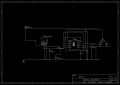
hi guys im trying to make 24v to 5v/12v pwm controller with a potentiometer to go onto a pcb this is the rough idea i could be totally wrong on this and its a very messy schematic but just wanted some opinions and a little bit of help because ive only ever made super basic ideas
the idea is this board will take 24v convert it down to a voltage 5v to run the 555 timer which allows me to control the speed of some pwm fans with an potentiometer
im rather sure ive messed this one up but would love to have some help to get this perfect
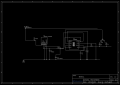
the idea is this board will take 24v convert it down to a voltage 5v to run the 555 timer which allows me to control the speed of some pwm fans with an potentiometer
im rather sure ive messed this one up but would love to have some help to get this perfect
Attachments
-
 51.4 KB Views: 15