24v PWM to 12v PWM fan

MisterBill2

Joined Jan 23, 2018
28,013
Do you have a 12 volt power supply that can run the 12 volt fan motor? If so, the very first thing to try will be to substitute the 12 volt supply in place of the 24 volt supply. That will probably work and be all that you need to do. If not, then more changes may be needed.
 
Last edited:

Thread Starter

AndersL

Joined Mar 22, 2022
12
Do you have a 12 volt power supply that can run the 12 volt fan motor? If so, the very first thing to try will be to substitute the 12 volt supply in pace of the 24 volt supply. That will probably work and be al that you need to do. If not, then more changes may be needed.
Sorry for my bad explanation.
I do have a 12v power source but the issue is that the 24v PWM comes in two wires so I don't have a dedicated PWM source.

Best regards
Anders
 

MisterBill2

Joined Jan 23, 2018
28,013
OK, now it is a bit confusing. But I am guessing then that you have a 24 volt PWM control signal, referenced to the power common, and that you want to use that 24 volt PWM signal to control your 12 volt fan. Quite a different case..
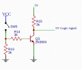
In that case, the circuit will work, but the R15 resistance may need to be changed and also the transistor current handling ability may need to be increased..
But if the PWM signal is just being passed on to another PWM control transistor, then the circuit may work as shown.
 

Thread Starter

AndersL

Joined Mar 22, 2022
12
OK, now it is a bit confusing. But I am guessing then that you have a 24 volt PWM control signal, referenced to the power common, and that you want to use that 24 volt PWM signal to control your 12 volt fan. Quite a different case..
In that case, the circuit will work, but the R15 resistance may need to be changed and also the transistor current handling ability may need to be increased..
But if the PWM signal is just being passed on to another PWM control transistor, then the circuit may work as shown.
I'll try to explain the scenario better.

I have:
A 24v PWM from a controller board, the whole board runs 24v, with + and - leads to a fan for variable cooling airflow.
An external 12v power source.

I need to replace the 24v rated stock fan with a 12v fan keeping the variable cooling airflow.
I've read that I can't use a buck converter on a PWM signal as the signal is too fast for the buck which will result in a constant 12v feed from the buck.

Been googling a lot and found the previously mentioned thread and circuit which sounds like the right thing.

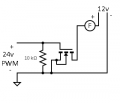
Also found others which uses a FET, like this circuit (not sure if I drew the FET the right way).
With the FET examples I found some warnings that most FETs have a Vgs of 20v as I have 24v I'm not sure if it'll work or burn up.
 

Attachments

MisterBill2

Joined Jan 23, 2018
28,013
OK, now we have the whole description. The present controller is a "black box" with a 24 volt input and 2 wires feeding a 24 volt motor that you want to replace with a 12 volt DC motor.
A pure guess is that the controller board also controls other stuff and so just replacing the 24 volt supply with a 12 volt supply is not an option. Or possibly the present controller board is mains powered and not 24 volts powered.
In either case, that very simple circuit is not the best choice because the series transistor will need to be adequate for the maximum motor current.
An effective but not most efficient option is to simply put a resistor in series with the 12 volt fan motor to reduce the voltage. What we do not know is the current that the motors draw at any running condition. Is the 12 volt motor to provide the same air flow as the 24 volt motor? Or is the intention to have a reduced air flow?
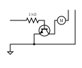
A more efficient but more complicated option is to use that 24 volt PWM signal, with a current limiting resistor, as the base drive for an NPN power transistor in series with the negative connection from the 12 volt motor. That will be much more efficient, but much more complex. The negative connection from the PWM controler wil be common with the negative side of the 12 volt power supply, that may, or not, be a problem, depending on what else is connected to the supplies.
 

Thread Starter

AndersL

Joined Mar 22, 2022
12
A pure guess is that the controller board also controls other stuff and so just replacing the 24 volt supply with a 12 volt supply is not an option. Or possibly the present controller board is mains powered and not 24 volts powered.
In either case, that very simple circuit is not the best choice because the series transistor will need to be adequate for the maximum motor current.
An effective but not most efficient option is to simply put a resistor in series with the 12 volt fan motor to reduce the voltage. What we do not know is the current that the motors draw at any running condition. Is the 12 volt motor to provide the same air flow as the 24 volt motor? Or is the intention to have a reduced air flow?
A more efficient but more complicated option is to use that 24 volt PWM signal, with a current limiting resistor, as the base drive for an NPN power transistor in series with the negative connection from the 12 volt motor. That will be much more efficient, but much more complex. The negative connection from the PWM controler wil be common with the negative side of the 12 volt power supply, that may, or not, be a problem, depending on what else is connected to the supplies.
Correct, the controller does lots of things and replacing the 24v power supply is not an option.
The intention is to have approximately the same airflow.
There will only be fans connected to the 12v power source as a couple will be running at full power all the time.

If I go with the efficient solution, could you point me in the right direction of which components that would be suitable?
Would a 2n2222 suffice?
For the current limiting resistor I haven't got a clue what to go for.

I really appreciate you taking time to help a novice!

Best Regards
Anders
 

crutschow

Joined Mar 14, 2008
38,683
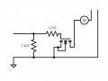
The circuit with a N-MOSFET in your post #5 should work.
To keep the gate voltage to 12V maximum, change the 10kΩ resistor to 1kΩ, and add a 1kΩ resistor in series with that resistor and the MOSFET gate.
 

MisterBill2

Joined Jan 23, 2018
28,013
Given that we have no hint at the amount of current that the motor will draw, I am still guessing that it will be quite a bit. For the same amount of air as the 24 volt fan, about twice the current, because the power will be about the same. Not a small load that the 2N2222 will pass. So prior to suggesting a transistor, we must know the current.
 

Thread Starter

AndersL

Joined Mar 22, 2022
12
Given that we have no hint at the amount of current that the motor will draw, I am still guessing that it will be quite a bit. For the same amount of air as the 24 volt fan, about twice the current, because the power will be about the same. Not a small load that the 2N2222 will pass. So prior to suggesting a transistor, we must know the current.
Sorry about that the fan draws 0.5A max at 12v.
 

MisterBill2

Joined Jan 23, 2018
28,013
OK, that is more than I would switch with a 2N2222. Because the PWM was originally driving a motor, you will have quite a bit of base drive available. You could use a serious power transistor like a 2N3055, which is good for ten amps or more, or a more closelyrated power transistor with a To220 case style .
 

Thread Starter

AndersL

Joined Mar 22, 2022
12
Noted.

A more efficient but more complicated option is to use that 24 volt PWM signal, with a current limiting resistor, as the base drive for an NPN power transistor in series with the negative connection from the 12 volt motor. That will be much more efficient, but much more complex. The negative connection from the PWM controler wil be common with the negative side of the 12 volt power supply, that may, or not, be a problem, depending on what else is connected to the supplies.
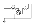
Would the circuit look something like this?
 

Attachments

Top