Facebook
 Google
 GitHub
 Linkedin
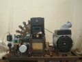
Speed controller, 24 volt DC, Electric motor,
I have a project I have been working on, that has me out of my depth with regard to my knowledge, as I am a very basic electronic hobbies.
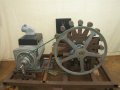
It comprises of a 24V D.C electric motor, 200W, 3,000 rpm, 13A. which has a pulley, a belt from this attaches to a pulley on a drive shaft, where a flywheel is situated, and on the other end, is a pulley, with another belt, that goes to a pulley on a 230v AC alternator.
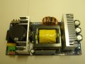
The motor is controlled by a Electromen EM-285 DC-Motor speed regulator 12 / 24V 20A. The regulator has three adjustable potentiometer, a Range trim, Current limit, and load compensation.
On the leaflet that came with the regulator for the installation, there is information that someone who works with electric motors, and speed controllers, which have potentiometer. Will know how to go about adjusting them to get the optima setting’s. But which has left me slightly baffled with my basic knowledge of electric motors, and electronics.
So I contacted the manufactures to see if they could help me, unfortunately they just repeated what was on the leaflet. But they did go off script a little, to quote from there email “There is no specific guidelines on setting the current-limit, I suggest experimenting until you find something that suits the application in question, start low and then increase”
So I experimented and found that if I sent the Range trim at a certain setting, and the current at another, the load compensation I left at zero.
With just the belt attached from the electric motor to the drive shaft, when I turned on the speed regulator, and increased the speed setting, the shaft started turning, I further increased the speed, and it picked up, and was moving very fast.
I then turn the speed down, and it only slowly lost speed, due to the motion of the flywheel. Until it was just turning over, and then I could slowly turn the speed up to a 100% again, and the flywheel would be whizzing around.
Next I attached the belt from the pulley on the drive shaft to the one on the alternator. Turned on the speed regulator, and slowly increased the speed, but this is when I found I had a problem, it would only rotate slowly. I put the speed controller up to 100% but it made know different to the speed.
The alternator shaft runs on two bearing, you can spin the pulley on it, with your hand, and it will do a couple of revolution before it stops, so there is know great resistants from the alternator spinning.
Also there is not a great difference in the force one has to use to spinning the flywheel by hand with just the electric motor being connected to the drive shaft. To when I then attach the belt from the pulley, to the alternator, and then spun it by hand.
But logic dictates, that I lost the speed, that I had before, (which I must point out was really fast). When I attached the other belt that goes to the Alternator.
So is the answer to the lost of speed, down to the adjustments of the Potentiometer, to be quite frank, Range trim, Current Limit, and especially Load compensation, I have a lack of knowledge and experience of working with.
I did go online to see if I could improve my knowledge, which I did to some extent.
So I did a little experiment, and increased the Current limit which certainly made a difference to the speed. As the test was progressing there was a smell of melting plastic. Looking at this fuse, that, protects the electric motor which is a spade type, that are used in motor car, the plastic casing was melting!, it was acutely bubbling! but the fuse had not blown, so I turn off the power. Let everything cool down, put a new fuse in, and did a quick test, and everything worked o.k, so nothing else was damaged.
Any thoughts, and suggestion on what the problem is, and how to go about fixing it, would be much appreciated.
I have a project I have been working on, that has me out of my depth with regard to my knowledge, as I am a very basic electronic hobbies.
It comprises of a 24V D.C electric motor, 200W, 3,000 rpm, 13A. which has a pulley, a belt from this attaches to a pulley on a drive shaft, where a flywheel is situated, and on the other end, is a pulley, with another belt, that goes to a pulley on a 230v AC alternator.
The motor is controlled by a Electromen EM-285 DC-Motor speed regulator 12 / 24V 20A. The regulator has three adjustable potentiometer, a Range trim, Current limit, and load compensation.
On the leaflet that came with the regulator for the installation, there is information that someone who works with electric motors, and speed controllers, which have potentiometer. Will know how to go about adjusting them to get the optima setting’s. But which has left me slightly baffled with my basic knowledge of electric motors, and electronics.
So I contacted the manufactures to see if they could help me, unfortunately they just repeated what was on the leaflet. But they did go off script a little, to quote from there email “There is no specific guidelines on setting the current-limit, I suggest experimenting until you find something that suits the application in question, start low and then increase”
So I experimented and found that if I sent the Range trim at a certain setting, and the current at another, the load compensation I left at zero.
With just the belt attached from the electric motor to the drive shaft, when I turned on the speed regulator, and increased the speed setting, the shaft started turning, I further increased the speed, and it picked up, and was moving very fast.
I then turn the speed down, and it only slowly lost speed, due to the motion of the flywheel. Until it was just turning over, and then I could slowly turn the speed up to a 100% again, and the flywheel would be whizzing around.
Next I attached the belt from the pulley on the drive shaft to the one on the alternator. Turned on the speed regulator, and slowly increased the speed, but this is when I found I had a problem, it would only rotate slowly. I put the speed controller up to 100% but it made know different to the speed.
The alternator shaft runs on two bearing, you can spin the pulley on it, with your hand, and it will do a couple of revolution before it stops, so there is know great resistants from the alternator spinning.
Also there is not a great difference in the force one has to use to spinning the flywheel by hand with just the electric motor being connected to the drive shaft. To when I then attach the belt from the pulley, to the alternator, and then spun it by hand.
But logic dictates, that I lost the speed, that I had before, (which I must point out was really fast). When I attached the other belt that goes to the Alternator.
So is the answer to the lost of speed, down to the adjustments of the Potentiometer, to be quite frank, Range trim, Current Limit, and especially Load compensation, I have a lack of knowledge and experience of working with.
I did go online to see if I could improve my knowledge, which I did to some extent.
So I did a little experiment, and increased the Current limit which certainly made a difference to the speed. As the test was progressing there was a smell of melting plastic. Looking at this fuse, that, protects the electric motor which is a spade type, that are used in motor car, the plastic casing was melting!, it was acutely bubbling! but the fuse had not blown, so I turn off the power. Let everything cool down, put a new fuse in, and did a quick test, and everything worked o.k, so nothing else was damaged.
Any thoughts, and suggestion on what the problem is, and how to go about fixing it, would be much appreciated.