2 stage audio amplifier with an emitter follower

Thread Starter

Ivan Trigueiro

Joined Jun 6, 2018
4
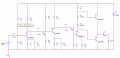
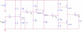
Hey guys, my teacher told us to make a project that has 2 amplifiers stage and docked to the second stage is supposed to be an emitter follower circuit, it will be a 50mV AC signal from 20Hz to 20kHz. Also the first stage HAS to be a common emitter. And we have to use a 15V DC.
He expect us to get a max gain in this bandwidth, i.e. the load signal must remain constant (I don't know really get this part).

So I came up with a couple of schematics, but I'm struggling to find the resistors and capacitors values. Specially capacitors.

My english might be a little rusty, sorry for that.
 

Attachments

dl324

Joined Mar 30, 2015
18,225
Welcome to AAC!

You posted two different schematics. Which one are you using? What gain did you design for?
 

Thread Starter

Ivan Trigueiro

Joined Jun 6, 2018
4
Thanks!

Yeah I made two schematics, actually I made five or six, I'm trying to decide what is the best one yet, but I'm going with the second for now.

The teacher said nothing about the gain, only that it had to be max on that bandwidth, I'm also struggling on what to do with the gain.

I asked another one of my teachers and he said that if the gain is too high on the first stage, the noise will also be high, so I got confused.

By my calculations the first stage gain was 107, that is for schematic 1-Project.
 
Last edited:

Ylli

Joined Nov 13, 2015
1,092
Just at a glance... First circuit, Q5 is drawn wrong, the emitter and collector need to be swapped. No bias on Q3 (resistor from base of Q3 to Q5 emitter would be a good place to get the bias from). Interstage and emitter bypass caps appear unreasonably large.

"project that has 2 amplifiers stage and docked to the second stage is supposed to be an emitter follower circuit,"

You've got three stages PLUS a full class AB output stage. Is this really what the teacher wants?
 

Thread Starter

Ivan Trigueiro

Joined Jun 6, 2018
4
Yes, he said that it could be considered a three stage aswell, that push and pull circuit I copied from one of his classes, he said it's ok to use it.

But the problem i had with the first circuit was the gain, because after the 2 amplifications the voltage marker I put there, after the coupling capacitor, was giving me close to 500V from simulation. So I've been tinkering with the circuit to lower that.
 

dl324

Joined Mar 30, 2015
18,225
This statement:
Yes, he said that it could be considered a three stage aswell, that push and pull circuit I copied from one of his classes, he said it's ok to use it.
is in conflict with your first post:
my teacher told us to make a project that has 2 amplifiers stage and docked to the second stage is supposed to be an emitter follower circuit
So which is it? Class AB or an emitter follower? Three stages or 4?
 

Thread Starter

Ivan Trigueiro

Joined Jun 6, 2018
4
I'll try to translate the best I can.

These are the project specifications:

Mount a two-stage small signal amplifier on a PCB with an emitter follower powered by a DC source also designed and implemented by the two students. (I asked him if this could be considered a 3 stage amplifier because of the emitter follower coupled and he said yes).

The two-stage small signal amplifier must contain two amplifier stages. Coupled to the second stage should be an emitter follower with a 1k load.

The input signal will be a 50mV AC signal with varying frequencies of 20Hz to 20kHz, so the amplifier is expected to have a gain frequency range, that is, the output signal on the load must remain constant over the defined frequency band.
 

MrAl

Joined Jun 17, 2014
13,670
Hello,

It is easier to go with two stages plus one emitter follower. I'd do that intead. The other circuit with the diodes is much harder to analyze really if you need exact results.
 
Top