2 * 12 Volt Circuits input 1 output

Thread Starter

Jason Finlayson

Joined Aug 4, 2018
5
Hi
I am looking to finalise a project I have stalled for quite some time.
I have a vehicle that when garaged it connected to a charger (24 Volt)

The requirement is that I am able to maintain charge for a tablet and a couple of radios whilst its garaged.
I have a 240v/12-volt transformer that gets plugged in at the same time as the 24v truck charger
At this point, the truck is electrically isolated by a big kill switch which allows you to plug in the 24-volt charger.

When the truck is about to go out its unplugged from these two independent power supplies, the kill switch is turned off and the truck can start.

The radios have a 24v to a 12volt transformer which has ample capacity to also supply the 12-volt circuit for the tablet.
Max peak power is 10 amps

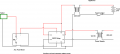
I am told I need a DPDT relay to achieve this.

I have had a look around the web and see more lots of wiring diagrams for dpdt but it seems that I want the reverse of all the examples seen so far.
As I want two inputs to supply one output.

So my goal is no matter what configuration the truck is in either operational or garaged I want to constantly feed power to the tablet and radios.

Can someone assist with a DPDT wiring example that fits the bill and hopefully an example part number so I can get the correct one.

Thanks & Regards
Jason
 

ericgibbs

Joined Jan 29, 2010
18,841
Hi Jason,
Is this digram showing how the DPDT switch will be connected.?
Selects either Input #1 or Input #2 as a voltage source, if not, mark up the diagram and we will modify the diagram.
E
 

Attachments

dendad

Joined Feb 20, 2016
4,472
Why not keep the 24V to 12V supply connected to the 24V truck battery all the time?
The 24V charger would be able to power the radios while charging the batteries too.
Or am I missing something?
 

Thread Starter

Jason Finlayson

Joined Aug 4, 2018
5
Why not keep the 24V to 12V supply connected to the 24V truck battery all the time?
The 24V charger would be able to power the radios while charging the batteries too.
Or am I missing something?
Why not keep the 24V to 12V supply connected to the 24V truck battery all the time?
The 24V charger would be able to power the radios while charging the batteries too.
Or am I missing something?

Not missing something, just not something we are allowed to tamper with.
 

Thread Starter

Jason Finlayson

Joined Aug 4, 2018
5
This is what I think I need to do? Not sure how the common comes into play.

NC + Truck Running (Input 12 VDC)
NC - Truck Running
NO + Truck On Charge (Input 12 VDC)
NO - Truck On Charge
COM + ????
COM - ????
Coil + Output Tablet & Radios (output 12VDC)
Coil - Output Tablet & Radios
 

dendad

Joined Feb 20, 2016
4,472
So I take it the 24V to 12V regulator is disconnected when the truck is garaged, and the kill switch isolates the 24V batteries from the vehicle.
A large diode bridge (easier than a couple of diodes) could be used from the output of the 24V to 12V regulator and the 12V external power supply.
That way you will not need a switch and the radios will run from either.
About a volt will be lost over the bridge but the 24V to 12V regulator could be adjusted up a bit if that proves to be a problem.
Bridge2.jpg
Connect the 12 external supply to one AC terminal, marked "~", the 24V to 12V regulator output to the other "~" terminal, and the radios to the "+" terminal.
The "-" terminal is not used.
This bridge rectifier can be bolted down to the truck metalwork.
Rectifiers like this are available in quite high current ratings.
Here is just one...
https://au.mouser.com/ProductDetail...=sGAEpiMZZMtQ8nqTKtFS/MRt2/0z7Bct866kwxpWb6Q=
 

Thread Starter

Jason Finlayson

Joined Aug 4, 2018
5
Here is my attempt at a drawing. If I hand drew it you would have no chance of reading it.
I am hoping that assists with what I am trying to achieve. The relay is the component I am struggling to get my head around.
Am I on the right track with the way the NO also connects with the coil?


Attachments

dendad

Joined Feb 20, 2016
4,472
That looks like it will work.When the truck is isolated, power goes from the external 12V supply to the tablet via the NC to C contacts.
With the isolator on, the relay is operated from the 24V to 12V supply, and power will then go from that supply to the tablet via the NO and C contacts.
Oh, the power supplies as shown are not the correct symbol. Just a box will be better. Transformers are part of the supply but transformers are AC in and AC out only.
You will not need to switch the 0V lines, just the +12V.
The diode bridge I posted above is a lot easier way to go.
 

Thread Starter

Jason Finlayson

Joined Aug 4, 2018
5
That looks like it will work.When the truck is isolated, power goes from the external 12V supply to the tablet via the NC to C contacts.
With the isolator on, the relay is operated from the 24V to 12V supply, and power will then go from that supply to the tablet via the NO and C contacts.
Oh, the power supplies as shown are not the correct symbol. Just a box will be better. Transformers are part of the supply but transformers are AC in and AC out only.
You will not need to switch the 0V lines, just the +12V.
The diode bridge I posted above is a lot easier way to go.
It worked thanks. I will get my head around diode bridges one day and have a crack at that.
 
Top