16x2 LCD I2C screen issue

Thread Starter

Vilius_Zalenas

Joined Jul 24, 2022
169
Hello,

I am working on a project where I have to establish the LCD screen driven by a PIC32MK1024MCM064 via I2C communication. I ran into a strange problem of not being able to address the I2C screen.

The screen I am using: Display Development Tools Grove - 16 x 2 LCD (Black on Red). Manufacturer part number: 104020112.

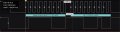
I am just starting to develop and test the code, so there is high possibility of many things not being right at the moment, but I can see my typical I2C data packet structure on the logic analyzer, so I believe the I2C setup in the MCU code is right. But as you can see in the analyzer, the LCD screen is not sending an ACK bit. What is more, There is absolutely no information of I2C address of the LCD screen in the datasheet, so I contacted the manufacturer and they redirected me to Git repository where they posted an arduino adapted code. So the only information source I could take the I2C address of the LCD was this line in their header file.

#define LCD_ADDRESS (0x7c>>1)

I am addressing the screen with an address of 0b 00111110

I am aware of bit shift operations and the R/W bit meaning in the I2C code, but this is the first time I see such strange definition in the I2C domain. I am not sure what would this code be in pure binary or hex form, because I am taking it for granted that the R/W is always zero in this situation, as I am only writing to the screen. Have you got any observations or ideas that could help me address the LCD properly or get rid of that NACK bit and replace with an ACK bit? :D

P.S (I am not posting the full MCU code as it is irrelevant in this topic, I believe)

Want to thank you in advance.


Git repository: https://github.com/Seeed-Studio/Grove_LCD_RGB_Backlight

I2C packet.jpg
 

Ian Rogers

Joined Dec 12, 2012
1,136
I don't shift the address... They only do that on Arduino... Arduino and other high level platforms automatically append the R/W bit, but Microchip doesn't, they add it.. So the address should be 0x7C.. BUT!!!! only if the address lines are High.

Again with the BUT!! If its a PCF8574 the top nibble is 0x4x.. My address was 0x4E..
 

Thread Starter

Vilius_Zalenas

Joined Jul 24, 2022
169
So I found out my mistake, the address was indeed 0x7C but I declared already 8 bit address including RW bit, when I should have declared 7 bit address RW bit being determined and generated by the software. I am getting the ACK bits from my LCD screen now.

However, another strange thing happened. After the data packet has been acknowledged SCL does not come back to the high state and the program jams. Of course I ensured all the hardware things such as wiring bypass capacitors etc... I also read about such problems being related to the clock stretching, but since there are only 2 devices on the I2C bus (master and slave) I disabled the clock stretching in the PIC32 software. Have you got any idea, why I could be getting clock stretching? Want to thank you in advance.

PIC32 code:

C:
// PIC32MK1024MCM064
// DEVCFG3
#pragma config USERID = 0xFFFF          // Enter Hexadecimal value (Enter Hexadecimal value)
#pragma config PWMLOCK = OFF            // PWM IOxCON lock (PWM IOxCON register writes accesses are not locked or protected)
#pragma config FUSBIDIO2 = ON           // USB2 USBID Selection (USBID pin is controlled by the USB2 module)
#pragma config FVBUSIO2 = ON            // USB2 VBUSON Selection bit (VBUSON pin is controlled by the USB2 module)
#pragma config PGL1WAY = OFF            // Permission Group Lock One Way Configuration bit (Allow multiple reconfigurations)
#pragma config PMDL1WAY = OFF           // Peripheral Module Disable Configuration (Allow multiple reconfigurations)
#pragma config IOL1WAY = OFF            // Peripheral Pin Select Configuration (Allow multiple reconfigurations)
#pragma config FUSBIDIO1 = ON           // USB1 USBID Selection (USBID pin is controlled by the USB1 module)
#pragma config FVBUSIO1 = ON            // USB2 VBUSON Selection bit (VBUSON pin is controlled by the USB1 module)
// DEVCFG2
#pragma config FPLLIDIV = DIV_1         // System PLL Input Divider (1x Divider)
#pragma config FPLLRNG = RANGE_BYPASS   // System PLL Input Range (Bypass)
#pragma config FPLLICLK = PLL_FRC     // System PLL Input Clock Selection (FRC is input to the System PLL)
#pragma config FPLLMULT = MUL_2         // System PLL Multiplier (PLL Multiply by 1)
#pragma config FPLLODIV = DIV_2        // System PLL Output Clock Divider (2x Divider)
#pragma config BORSEL = HIGH            // Brown-out trip voltage (BOR trip voltage 2.1v (Non-OPAMP deviced operation))
#pragma config UPLLEN = OFF             // USB PLL Enable (USB PLL Disabled)
// DEVCFG1
#pragma config FNOSC = FRC              // Oscillator Selection Bits (Internal Fast RC (FRC))
#pragma config DMTINTV = WIN_0          // DMT Count Window Interval (Window/Interval value is zero)
#pragma config FSOSCEN = OFF            // Secondary Oscillator Enable (Disable Secondary Oscillator)
#pragma config IESO = OFF               // Internal/External Switch Over (Disabled)
#pragma config POSCMOD = OFF            // Primary Oscillator Configuration (Primary osc disabled)
#pragma config OSCIOFNC = OFF           // CLKO Output Signal Active on the OSCO Pin (Disabled)
#pragma config FCKSM = CSDCMD           // Clock Switching and Monitor Selection (Clock Switch Disabled, FSCM Disabled)
#pragma config WDTPS = PS1              // Watchdog Timer Postscaler (1:1)
#pragma config WDTSPGM = STOP           // Watchdog Timer Stop During Flash Programming (WDT stops during Flash programming)
#pragma config WINDIS = NORMAL          // Watchdog Timer Window Mode (Watchdog Timer is in non-Window mode)
#pragma config FWDTEN = OFF             // Watchdog Timer Enable (WDT Disabled)
#pragma config FWDTWINSZ = WINSZ_25     // Watchdog Timer Window Size (Window size is 25%)
#pragma config DMTCNT = DMT31           // Deadman Timer Count Selection (2^31 (2147483648))
#pragma config FDMTEN = OFF             // Deadman Timer Enable (Deadman Timer is disabled)
// DEVCFG0
#pragma config DEBUG = OFF              // Background Debugger Enable (Debugger is disabled)
#pragma config JTAGEN = OFF             // JTAG Enable (JTAG Disabled)
#pragma config ICESEL = ICS_PGx3        // ICE/ICD Comm Channel Select (Communicate on PGEC3/PGED3)
#pragma config TRCEN = OFF              // Trace Enable (Trace features in the CPU are disabled)
#pragma config BOOTISA = MIPS32         // Boot ISA Selection (Boot code and Exception code is MIPS32)
#pragma config FECCCON = ECC_DECC_DISABLE_ECCON_WRITABLE// Dynamic Flash ECC Configuration Bits (ECC and Dynamic ECC are disabled (ECCCON<1:0> bits are writable))
#pragma config FSLEEP = OFF             // Flash Sleep Mode (Flash is powered down when the device is in Sleep mode)
#pragma config DBGPER = PG_ALL          // Debug Mode CPU Access Permission (Allow CPU access to all permission regions)
#pragma config SMCLR = MCLR_NORM        // Soft Master Clear Enable (MCLR pin generates a normal system Reset)
#pragma config SOSCGAIN = G3            // Secondary Oscillator Gain Control bits (Gain is G3)
#pragma config SOSCBOOST = ON           // Secondary Oscillator Boost Kick Start Enable bit (Boost the kick start of the oscillator)
#pragma config POSCGAIN = G3            // Primary Oscillator Coarse Gain Control bits (Gain Level 3 (highest))
#pragma config POSCBOOST = ON           // Primary Oscillator Boost Kick Start Enable bit (Boost the kick start of the oscillator)
#pragma config POSCFGAIN = G3           // Primary Oscillator Fine Gain Control bits (Gain is G3)
#pragma config POSCAGCDLY = AGCRNG_x_25ms// AGC Gain Search Step Settling Time Control (Settling time = 25ms x AGCRNG)
#pragma config POSCAGCRNG = ONE_X       // AGC Lock Range bit (Range 1x)
#pragma config POSCAGC = Automatic      // Primary Oscillator Gain Control bit (Automatic Gain Control for Oscillator)
#pragma config EJTAGBEN = NORMAL        // EJTAG Boot Enable (Normal EJTAG functionality)
// DEVCP
#pragma config CP = OFF                 // Code Protect (Protection Disabled)
// SEQ
#pragma config TSEQ = 0x0               // Boot Flash True Sequence Number (Enter Hexadecimal value)
#pragma config CSEQ = 0xFFFF            // Boot Flash Complement Sequence Number (Enter Hexadecimal value)
//-------------------------------------------------------------------------------------------------------------------------------------------------------------------------------------------------------------
#include <xc.h>                      
#include <toolchain_specifics.h>    
#include <stddef.h>                
#include <stdint.h>                
#include <stdbool.h>                
#include <stdlib.h>
#include "stdio.h"
#include <sys/attribs.h>
//-------------------------------------------------------------------------------------------------------------------------------------------------------------------------------------------------------------
#define CPU_CLOCK_FREQUENCY 8000000
#define _CP0_GET_COUNT()  _mfc0 (_CP0_COUNT, _CP0_COUNT_SELECT)
//------------------------------------------------------------------------------------------------------------------------------------------------------------------------------------------------------------
#define MASTER_WRITE_LCD (0B1111100)     //  7 BITS ONLY Address of 0x7C Last bit is R/W (1 for reading, and 0 for writing)
//------------------------------------------------------------------------------------------------------------------------------------------------------------------------------------------------------------
void delay_ms ( uint32_t delay_ms)
{
    uint32_t startCount, endCount;

    endCount=((CPU_CLOCK_FREQUENCY/1000)*delay_ms)/2;

    startCount=_CP0_GET_COUNT();
    while((_CP0_GET_COUNT()-startCount)<endCount);
}
//-----------------------------------------------------------------------------------------------------------------------------------------------------------------------------------------------
void I2C__initialization(void){
 
    //The datasheet declares that when the I2C module is enabled pins are assigned automatically
    //(For I2C module nr.1 SCL is pin 5 and SDA is pin 6 ) and TRIS bits are overriden anyway.
    //I believe there is nothing else to do with I2C pin setup other than enabling the I2C module
 
    //PIC is operating in master mode, so address and address mask register are irrelevant for this application.
 
    //PB2CLK is same as SYSCLK here (8Mhz)
 
    ANSELG = 0xFFFFFE7F;          //Enable digital inputs for I2C pins (Clear ANSEL RG7 and RG8)    
 
    I2C1BRG = 0x00000010;         //Baud rate setup register (Here 50 kHz for the 100kb/s data rate)
    //---------------------------------------------------------------------------
    I2C1CON = 0x00000000;         //Resetting register to clear all bits (to ensure right setup)
    I2C1CONbits.SDAHT = 0b1;      //Minimum of 300 ns hold time on SDA after the falling edge of SCL
    I2C1CONbits.SIDL = 0b1;       //Discontinue module operation when device enters Idle mode
    I2C1CONbits.SCLREL = 0b1;     //Release SCL clock
    I2C1CONbits.STREN = 0b0;      //Disable software or receive clock stretching
    I2C1CONbits.DISSLW = 0b1;     //Slew rate control is disabled
    I2C1CONbits.SMEN = 0b0;       //Disable SMBus input thresholds
    I2C1CONbits.ON = 0b1;         //Enable I2C module
}
//-----------------------------------------------------------------------------------------------------------------------------------------------------------------------------------------------
void I2C__state(void){
    while( (I2C1CON & 0x0000001F) || (I2C1STAT & 0x00000004) );  //Checking is the I2C bus is idle, waiting until it becomes idle (checking all I2C status bits)
}
//-----------------------------------------------------------------------------------------------------------------------------------------------------------------------------------------------
void I2C__Start(void){
    I2C__state();
    I2C1CONbits.SEN = 0b1;     //Initiate Start condition on SDAx and SCLx pins
}
//-----------------------------------------------------------------------------------------------------------------------------------------------------------------------------------------------
void I2C__Stop(void){
    I2C__state();
    I2C1CONbits.PEN = 0b1;    //Initiate Stop condition on SDAx and SCLx pins
}
//-----------------------------------------------------------------------------------------------------------------------------------------------------------------------------------------------
void I2C_Repeated_Start(void){
    I2C__state();
    I2C1CONbits.RSEN = 0b1;   //Initiate Repeated Start condition on SDAx and SCLx pins
}
//-----------------------------------------------------------------------------------------------------------------------------------------------------------------------------------------------
void I2C__Write(uint8_t I2C_data){
    I2C__state();
    while(I2C1STATbits.TBF != 0);        //Ensuring the transmit buffer is completely empty before the new transmission
    while(I2C1STATbits.TRSTAT != 0);     //Ensuring the transmission has ended
    I2C1TRN = I2C_data;                  //Loading the data to the I2C transmit buffer for transmission
}
//-----------------------------------------------------------------------------------------------------------------------------------------------------------------------------------------------
uint8_t I2C__Read (uint8_t ACK){
   uint8_t data = 0;
   I2C__state();
   I2C1CONbits.RCEN = 0b1;            //Enables Receive mode for I2C
   while(I2C1STATbits.RBF != 0);      //Ensuring the receive buffer is completely empty before new reception
   data = (I2C1RCV & 0x000000FF);     //Extracting lower 8 bits of the I2C data from a 32 bit I2C receive register
   I2C1CONbits.ACKEN = ACK;
   return data;
}
//-----------------------------------------------------------------------------------------------------------------------------------------------------------------------------------------------
int main ( void )
{
    TRISAbits.TRISA7 = 1;    //Button input setup
 
    ANSELA = 0x00000000;     //Enable PORT A digital inputs (VERY IMPORTANT)

    TRISBbits.TRISB14 = 0;
    LATBbits.LATB14 = 0;     //LED 1
 
    TRISBbits.TRISB15 = 0;
    LATBbits.LATB15 = 0;     //LED 2
 
    TRISGbits.TRISG6 = 0;
    LATGbits.LATG6 = 0;      //LED 3
 
    I2C__initialization();
 
    while (1)
    {    
        //Background blinking leds
     
        LATBbits.LATB14 = 1;
        delay_ms(200);
        LATBbits.LATB14 = 0;
        LATBbits.LATB15 = 1;
        delay_ms(200);
        LATBbits.LATB15 = 0;
     
        if(!PORTAbits.RA7){    //Button press initiates I2C event
            LATGbits.LATG6 = 1;
            I2C__Start();
            I2C__Write(MASTER_WRITE_LCD);
            I2C__Write(0xE2);                 //This should display letter ,,b" according to the LCD symbol table, any letter in general just to see it working
            I2C__Stop();
            delay_ms(200);
            LATGbits.LATG6 = 0;
        }
         
    }
    return (EXIT_FAILURE);
}
 

Attachments

JohnInTX

Joined Jun 26, 2012
4,787
I'm not familiar with the PIC32 I2C (I use the 8 bit stuff) but try a few of these:

  • In MPLABX, stop the debugger and see where in the code is hung. If you are not using a debugger - use a debugger. PICkits, ICDs, Curiosity boards all have built in debugging. Finding out what the code is doing when it fails is the first step.
  • You can tell which device is pulling SCL down by disconnecting SCL from them one at a time. If disconnecting the PIC makes SCL rise, then your problem is in the master PIC. Slaves can also get confused and pull SCL. Knowing which device is in error will guide you.
  • You do not seem to be reading the ACK status after writing a byte. I don't know if it's a problem but you should do that in any case. The PIC32 I2C reference guide also mentions clearing the Master I2C interrupt after each byte. Not doing so might stop things up.
  • When you stop the code with the debugger, you can inspect the various status registers for a write collision, receive overflow etc.
  • Try writing more than the 2 bytes. If it writes more than 2 then stops again at the STOP generation then look there. If it ONLY writes 2 bytes then hangs, I'd look for some peripheral buffering issue.

All of this is pure speculation but if I were doing it, I'd start along those lines.

Good luck!
 

Attachments

Top